Table of Contents
Advertisement
Quick Links
© ELECTROLUX ZANUSSI S.p.A.
Spares & Service Documentation
Corso Lino Zanussi, 30
I - 33080 PORCIA /PN (ITALY)
Tel +39 0434 394850
Fax +39 0434 394096
Edition: 2001.08.28
2001.08 eb
Publication no.
599 34 85-05
IT/eb
1
SERVICE MANUAL
WASHING
WASHING MACHINES
AND WASHER-DRYERS
WITH TIMER
132 0558 1..
FUNCTIONALITY
VS81 (AKO)
599 34 85-05
Advertisement
Table of Contents

Related Manuals for Electrolux with VS81 timer


Summary of Contents for Electrolux with VS81 timer
-
Page 1: Service Manual
SERVICE MANUAL WASHING WASHING MACHINES AND WASHER-DRYERS WITH TIMER © ELECTROLUX ZANUSSI S.p.A. Publication no. 132 0558 1.. Spares & Service Documentation Corso Lino Zanussi, 30 FUNCTIONALITY I - 33080 PORCIA /PN (ITALY) 599 34 85-05 VS81 (AKO) Tel +39 0434 394850... - Page 2 2001.08 eb 599 34 85-05...
-
Page 3: Table Of Contents
CONTENTS GENERAL CHARA CTERISTICS ...................... 5 WASHING PROGRAMMES......................6 PUSH-BUTTONS FUNCTIONALITY................... 8 2.1.1 ON/OFF ..........................8 2.1.2 Half load ..........................8 2.1.3 Extra rinse.......................... 8 2.1.4 Rinse hold.......................... 8 2.1.5 Heavy soil .......................... 8 2.1.6 Cold wash.......................... 8 2.1.7 50°............................. 8 2.1.8 No spin .......................... - Page 4 TIMER DIAGRAM .......................... 27 BASIC ELECTRIC DIAGRAM......................28 WASHING MACHINES ......................28 WASHER-DRYERS......................... 29 OTHER OPTIONS........................30 KEY TO CIRCUIT DIAGRAM ....................30 TEST CYCLE AND TROUBLESHOOTING..................31 Test cycle..........................31 6.1.1 Operations to be performed during the first phase of test cycle..........32 6.1.2 Operations to be performed during the second phase of test cycle ........
-
Page 5: General Chara Cteristics
1 GENERAL FEATURES The VS81 timer, manufactured by AKO, is used in a number of front-loading washing machines and washer- dryers. front-loading appliances produced in Italy (Porcia) front-loading appliances produced in Spain (Alcalà) FUNCTIONALITY VS 81 (ZP) VS 81 (ZA) Traditional/with “Eco- Traditional/with “Eco- WASHING SYSTEM:... -
Page 6: Washing Programmes
2 WASHING PROGRAMMES "EUROPE" MODELS (cold water solenoid only) Models with fixed temperatures Models with adjustable temperatures Wash Wash COTTON - LINEN Rinses COTTON - LINEN Rinses (°C) (°C) WHITES/COLOUREDS 30-95 WHITES WITH PREWASH WITH PREWASH WHITES WHITES/COLOUREDS 30-95 COLOUREDS-FAST ----- DELICATE COLOUREDS -----... - Page 7 "UK" MODELS (warm and cold water solenoid) Models with fixed temperatures Models with adjustable temperatures Wash Wash COTTON - LINEN Rinses COTTON - LINEN Rinses (°C) (°C) WHITES/COLOUREDS WHITES WITH PREWASH 40-95 WITH PREWASH 40-95 WHITES WHITES/COLOUREDS COLOUREDS-FAST ----- DELICATE DELICATE COLOUREDS 30-40 COLOUREDS...
-
Page 8: Push-Buttons Functionality
2.1 PUSH-BUTTON FUNCTIONS 2.1.1 ON/OFF Switches the appliance ON and OFF. 2.1.2 Half load Eliminates one rinse in COTTON programmes (at first level). This function has no effect in the RINSE cycle (5). 2.1.3 Extra rinse Adds one rinse in COTTON cycles (at second level). This function has no effect in the RINSE cycle (5). 2.1.4 Rinse hold Stops the appliance with water in the tub at the end of the final rinse;... -
Page 9: Selectors Functionality
2.2 SELECTORS FUNCTIONALITY 2.2.1 Washing temperature selector An 8-position potentiometer can be used to reduce the washing temperature as shown in the table below: DELICATES- COTTON SYNTHETICS WOOL Position (°C) (°C) PREWASH SOAK (°C) Cold Cold Cold 60 (50 UK) 60 (50 UK) 60 (50 UK) 60 (50 UK) -
Page 10: Wash Load Selector
2.2.3 Wash load selector In some washing machines, a 3-position commutator can be used to modify the structure of the COTTON cycles according to the quantity of washing in the drum (the intermediate position corresponds to the standard programme). Selector COTTON 70 ÷... -
Page 11: Spin Speed And Rinse Hold Selector (9-Position)
2.2.5 Spin speed and rinse hold selector (9-position) In this case it is used a 9-position potentiometer. In the first position (rinse hold), the appliance stops leaving the water in the tub at the end of the final rinse. This function can be selected for COTTON, SYNTHETICS, DELICATES and WOOL cycles. -
Page 12: Cotton Programmes - Models With Fixed Temperatures
COTTON PROGRAMMES - MODELS WITH FIXED TEMPERATURES 10/07/01 COTTON (fixed temperatures OPTIONS VS81 90° Notes Press Cold Washing Extra Rinse Red. Auto Step Basic function Lev with pre- 90° 60° 40° No spin wash temp. load rinse hold spin wash. Fill+rinse+wash 2 L1+40°... -
Page 13: Synthetics And Mixed Fabrics Programmes - Models With Fixed Temperatures
PROGRAMMES FOR SYNTHETICS/MIXED FABRICS - MODELS WITH FIXED TEMPERATURES 10/07/2001 SYNTHETICS (Fixed temperatures OPTIONS VS81 60° Press 60° 40° 30° Rinses Cold Rinse Red. Auto Step Basic function Lev with pre- Wash time No spin Notes wash hold spin drying wash Fill+rinse+wash L1+40°... -
Page 14: Cotton Programmes - Models With Adjustable Temperatures
COTTON PROGRAMMES - MODELS WITH ADJUSTABLE TEMPERATURES 10/07/2001 COTTON (adjustable temperatures) OPTIONS VS81 Step Cold - 90° 70º - 90° 50º - 60° Cold Wash Half Extra Rinse Red. Auto Press. Basic functions Lev 30º - 40° No spin Notes wash time load... -
Page 15: Synthetics And Mixed Fabrics Programmes - Models With Adjustable Temperatures
PROGRAMMES FOR SYNTHETICS/MIXED FABRICS - MODELS WITH ADJUSTABLE TEMPERATURES 10/07/2001 SYNTHETICS (Adjustable temperatures) OPTIONS VS81 Cold - 50° Press 50º 30º - 40° 30° Rinses Cold Extra Red. Auto Step Basic functions with pre- Half load No spin Notes wash rinse spin wash... -
Page 16: Wool And Delicates Programmes - Models With Fixed And Adjustable Temperatures
2.3 WOOL AND DELICATES PROGRAMMES – Models with fixed and adjustable temperatures VS81 OPTIONS 10/07/01 WOOL-DELICATES (all) WOOL DELICATES Reduced Step Press. Basic functions Lev. Rinses Cold wash Rinse hold No spin Notes 30º - 40° 30º - 40° spin Drain L1<... -
Page 17: Spin Types
2.4 TYPES OF SPIN CYCLE 2.4.1 Anti-unbalancing during spinning The check for balancing of the wash load is performed while the drum rotates at a speed of 85 rpm, before the spin phase. If the wash load is unbalanced, the spin cycle is not carried out; after rotating the drum several times at low speed in alternate directions, the spin cycle is restarted. -
Page 18: Spin Sequences
2.4.4 Spin sequences Note: If the maximum times are exceeded (PTO – STO) the timer passes to the subsequent phase. 2001.08 eb 599 34 85-05... -
Page 19: Attention To The Operating Particularity
2.5 ATTENTION TO THE OPERATING PARTICULARITY! In order to avoid unnecessary operations on models with VS81 timers, we point put some particularity which characterise their operating. 2.5.1 Rapid advances in 90/60°C cotton cycles As may be seen from the timer diagrams, the programmes in question are started in steps 3 – 5. When the appliance is switched on, the timer advances rapidly to a position between the starting points for COTTON 60 and 40 programmes, during which the water fill takes place. -
Page 20: Technical Features
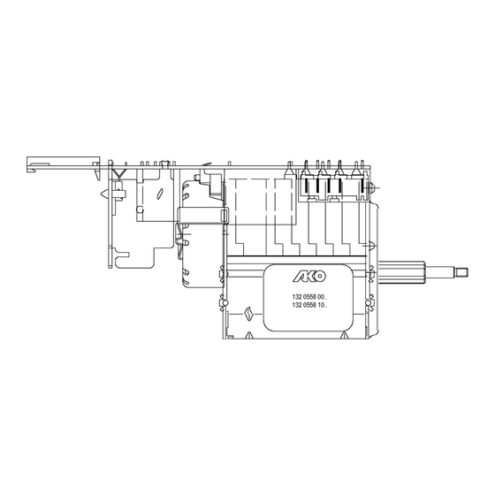
3 TECHNICAL FEATURES 3.1 HYBRID TIMER This timer consists of two main components: the electromechanical timer and an electronic board; the electronic board is soldered directly to the timer connectors. 1. Electronic control 2. Microprocessor 3. Timer motor 4. Electromechanical timer 3.2 Operatin principle of timer COMPONENTS IN APPLIANCE Door safety... -
Page 21: Configuration Of Timer Functions
Depending on the closure of a series of contacts (8-9-10), the timer transmits to the electronic control board (14) the codes which determine the operations to be carried out at the various steps. The electronic control board, on the basis of the appliance configuration and of the selected options (push- buttons and selectors) controls the washing cycle: •... -
Page 22: Selectors
3.3 SELECTORS 3.3.1 8-position selector This potentiometer (0-10000Ω) can have the following functions: § temperature regulator § washing time regulator § spin speed selector 3.3.2 9-position selector This selector can be used as speed regulator: the last position stops the appliance with water in tub. 1: rinse hold 2: no spin 9: maximum speed... -
Page 23: Description Of Main Functios
3.4 DESCRIPTIONS OF MAIN FUNCTIONS 3.4.1 Door lock The door safety device is powered through the closure of contacts of the main switch and by the G6.1-H3.2 timer contact. Few seconds after the starting, the door is locked and the device contact closes supplying the appliance (contact 5-4). -
Page 24: Control Of Pressure Switches Closure
3.4.4 Control of pressure switches closure The check of position of pressure switch contacts (empty or full) is detected by the electronic board (14) by means of two “sensing“ lines: § L1: 1 level (5) pressure switch check § L2: 2 level (6) pressure switch check 3.4.5 Control of washing temperature... -
Page 25: Motor
3.4.7 Motor The motor (15) is powered by the electronic control via a triac; the rotation inversions are effected by the commutation of two relays. Electronic control Rotor Stator Moto-protection Tachometric generator 3.4.8 Motor safety § Motor power Triac short-circuited If the Triac which powers the motor is short-circuited, the electronic control (14) disconnects the motor by switching the relays. -
Page 26: Drying (Washer-Dryers)
3.5 DRYING (WASHER-DRYERS) 3.5.1 Time switch drying The components of the drying circuit are powered by a two-sector time switch (it can vary in function of the model); the maximum time of drying is 120 minutes for both sectors. The last 10 minutes are dedicated to the cooling phase. Diagram of drying time switch type 12426685.. -
Page 27: Timer Diagram
4 TIMER DIAGRAM 2001.08 eb 599 34 85-05... -
Page 28: Basic Electric Diagram
5 BASIC CIRCUIT DIAGRAM 5.1 WASHING MACHINES 2001.08 eb 599 34 85-05... -
Page 29: Washer-Dryers
5.2 WASHER-DRYERS 2001.08 eb 599 34 85-05... -
Page 30: Other Options
5.3 OTHER OPTIONS 5.4 KEY TO CIRCUIT DIAGRAM Washing machines and washer dryers Washer dryers only 1. Interference supressor 17. Spin speed selector 32. Automatic drying contact 2. ON/OFF push button 18. Washing temperature selector 33. Drying timer motor 3. Pilot lamp 19. -
Page 31: Test Cycle And Troubleshooting
6 TEST CYCLE AND TROUBLESHOOTING 6.1 Test cycle Please find below a short cycle to be used to check the different functions of the appliance. Testing the VS81timer Phase Step - programme Functions control Performed operations Water drain until 1 level pressure switch EMPTY (3 min. -
Page 32: Operations To Be Performed During The First Phase Of Test Cycle
6.1.1 Operations to be performed during the first phase of the test cycle → Component to be → Functional check → Fault → Check with machine off Knob position Phase repaired/replaced Check the continuity of the power The WM does not switch on: the cable, the wiring and the suppressor Power cable, wiring, suppressor, Switching on... -
Page 33: Operations To Be Performed During The Second Phase Of Test Cycle
6.1.2 Operations to be carried out during the second phase of the test cycle → Component to be → Functional check → Fault → Check with machine off Knob position Phase repaired/replaced Timer or pressure switch blocked on Timer advance after a few Timer / 1 level pressure switch Timer does not advance... -
Page 34: Operations To Be Performed During The Third/Fourth Phase Of Test Cycle
6.1.3 Operations to be carried out during the third/fourth phases of the test cycle → Component to be → Functional check → Fault → Check with machine off Knob position Phase repaired/replaced Timer contact Timer Solenoid interrupted/blocked Solenoid valve Solenoid valve does not fill Wiring to solenoid valve Wiring / Connectors level water fill... -
Page 35: A ) Of Test Cycle
6.1.4 Operations to be carried out durong the drying phase (5 ) of the test cycle → Component to be → Functional check → Fault → Check with machine off Knob position Phase repaired/replaced Drying time switch contact faulty Drying time switch The drying phase is skipped Wiring faulty / interrupted Wiring... -
Page 36: Operations To Be Performed During The Drying Phase
6.1.5 Checking the commutator motor 1) Check the connector blocks (wiring) and check for detached or bent terminals. 2) Check for the presence of traces / residue / build-up of water or detergent, and identify the source. 3) Use a tester with a minimum scale of 40 Mohm to check for windings or other components that are connected to mass or poorly earthed (read ∞) across each terminal and the casing. -
Page 37: Timer Connectors
6.2 TIMER CONNECTORS (detach all connectors before measuring the contacts!) 6.2.1 Burns on the timer electronic board In case of burning of the printed circuit of the timer, check that the problem is not caused by another electrical component (short circuits, poor insulation, water leakage etc.).
Need help?
Do you have a question about the with VS81 timer and is the answer not in the manual?
Questions and answers