Table of Contents
Advertisement
NOTE: Read the entire instruction manual before starting the
installation.
Installation Instructions
High---Wall Duct ---Free Split Systems
PA13A / PW3CA Cooling Sizes 009---012
PA13N / PW3CN Cooling Sizes 012---024
PH13A / PW3HA HP Sizes 009---012
PH13N / PW3HN HP Sizes 012---024
TABLE OF CONTENTS
. . . . . . . . . . . . . . . . . . . . . . . . . . . . . . . . . . . . . . .
. . . . . . . . . . . . . . . . . . . . . . . . . . . . . . . . . . . . . . . . .
. . . . . . . . . . . . . . . . . . . . . . . . . . . . . . . . . . . . . .
. . . . . . . . . . . . . . . . . . . . . . . . . . . . . . . . . . . . .
. . . . . . . . . . . . . . . . . . . . . . . . . . . . . . .
INSTALL ALL POWER AND INTERCONNECTING WIRING
. . . . . . . . . . . . . . . . . . . . . . . . . . . . . .
. . . . . . . . . . . . . . . . . . . . . . . . . . . . . . . . . . . . . . . .
. . . . . . . . . . . . . . . . . . . . . . . . . . . . . .
PAGE
. . . . . . . . . . . . . . . . . . . . . . . . .
. . . . . . . . . . . . . . . . . . . . . . . . . .
. . . . . . . . . . . . . . . . . . . . . . .
. . . . . . . . . . . . . . . . . . . . . . .
. . . . . . . . . . . . . . . . . . . . .
. . . . . . . . . . . . . . . . . . . . .
. . . . . . . . . . . . . . . . .
. . . . . . . . . . . . . . . . . . .
2
3
3
3
4
4
5
6
6
7
8- -9
10
10
11
12
13
Advertisement
Table of Contents

Subscribe to Our Youtube Channel
Related Manuals for Payne PA13A/ PW3CA


Summary of Contents for Payne PA13A/ PW3CA
-
Page 1: Table Of Contents
High---Wall Duct ---Free Split Systems PA13A / PW3CA Cooling Sizes 009---012 PA13N / PW3CN Cooling Sizes 012---024 PH13A / PW3HA HP Sizes 009---012 PH13N / PW3HN HP Sizes 012---024 Installation Instructions TABLE OF CONTENTS PAGE PARTS LIST ........SAFETY CONSIDERATIONS . -
Page 2: Parts List
PARTS LIST Part Part Name of Part Name of Part Mounting Plate Mounting Plate Mounting Screw ST3.9x25 ---C ---H Mounting Screw A ST3.9x25 ---C ---H Anchor Anchor Remote Control Remote Control Remote Control Holder Remote Control Holder Mounting Screw B ST2.0x10 ---C ---H Mounting Screw B ST2.0x10 ---C ---H Remote Control Mounting screw B... -
Page 3: Safety Considerations
SAFETY CONSIDERATIONS GENERAL Installing, starting up, and servicing air- -conditioning equipment These instructions cover the installation, start- -up and servicing of can be hazardous due to system pressures, electrical components, PA13A, PA13N, PH13A, PH13N outdoor and PW3CA, PW3CN, and equipment location (roofs, elevated structures, etc.). PW3HA, PW3HN indoor units duct free systems. -
Page 4: Dimensions
DIMENSIONS - - INDOOR A07336 Model Size Operating Weight lb (kg) in. (mm) in. (mm) in. (mm) 32.09 (815) 11.02 (280) 7.68 (195) 17.6 (8) 35.67 (906) 11.26 (286) 9.25 (235) 25.3 (11.5) 49.21 (1250) 12.80 (325) 9.06 (230) 39.6 (18) 49.21 (1250) 12.80 (325) 9.06 (230) -
Page 5: Clearances
CLEARANCES - - INDOOR CEILING 6" (0.15m) min. 5" 5" (0.13m) (0.13m) min. min. (1.8m) FLOOR A07891 Fig. 3 --- Indoor unit clearance CLEARANCES - - OUTDOOR Air-inlet Air-outlet A07894 18k and 24k in. (mm) UNIT 9k and 12k in. (mm) 24 (610) 24 (610) 24 (610) -
Page 6: Installation Tips
INSTALLATION TIPS 1. Carefully remove the mounting plate, which is attached to the back of the indoor unit. Ideal installation locations include: 2. The mounting plate should be located horizontally and level Indoor Unit on the wall. All minimum spacings shown in Fig. 3, 4, and S A location where there are no obstacles near inlet and outlet area. -
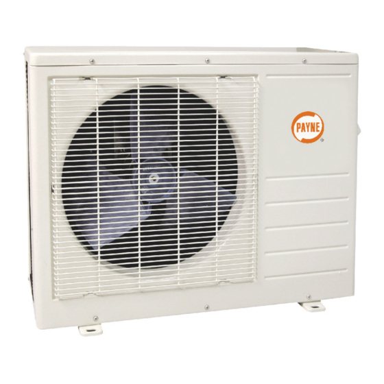
Page 7: Outdoor Unit Installation
If the installation location may be exposed to strong wind , use a ends until all the connections are made. wind baffle. Check with your Payne representative to obtain Bend tubing with bending tools to avoid kinks and flat spots. drawings for wind baffles. - Page 8 INSTALL ALL POWER AND INTERCONNECTING WIRING TO OUTDOOR UNITS 1. Mount outdoor power disconnect. CAUTION 2. Run power wiring from main box to disconnect per NEC and local codes. EQUIPMENT DAMAGE HAZARD 3. Remove field wiring cover from unit by loosening screws. Failure to follow this caution may result in equipment 4.
-
Page 9: Connection Diagrams
CONNECTION DIAGRAMS CONNECTING CABLE CONTROL CONTROL CONNECTING CABLE CONNECTING CABLE Notes: 1. Do not use thermostat wire for any connection between indoor and outdoor units. 2. All connections between indoor and outdoor units must be as shown. The connections are sensitive to polarity. 3. -
Page 10: To Outdoor Unit
INSTALL ALL POWER, INTERCONNECTING 8. Connect wiring from outdoor unit per connection diagram (see Fig. 13 and Fig. 15). WIRING, AND PIPING TO INDOOR UNIT. 9. Replace field wiring cover and close front cover of indoor 1. Run interconnecting piping and wiring from outdoor unit to unit. -
Page 11: System Vacuum And Charge
Deep Vacuum Method CAUTION The deep vacuum method requires a vacuum pump capable of pulling a vacuum of 500 microns and a vacuum gage capable of UNIT DAMAGE HAZARD accurately measuring this vacuum depth. The deep vacuum method is the most positive way of assuring a system is free of air and Failure to follow this caution may result in equipment liquid water. -
Page 12: Start- -Up
START- - UP Test Operation SYSTEM CHECKS Perform test operation after completing gas leak and electrical 1. Conceal the tubing where possible. safety check. (See Fig.. 20) 2. Make sure that the drain tube slopes downward along its en- tire length. 3. -
Page 13: Troubleshooting
TROUBLESHOOTING For ease of service, the systems are equipped with diagnostic code LEDs on the display panel or the front of the unit. If possible, display LEDs on both the indoor and outdoor units. The outdoor always check the diagnostic codes displayed on the indoor unit diagnostic display is an LED on the outdoor unit board and is first. - Page 14 Printed in U.S.A. Edition Date: 02/09 Copyright 2009 Payne Heating & Cooling S 7310 W. Morris St. S Indianapolis, IN 46231 Replaces: PA--- PH13--- PW3--- 2SI Manufacturer reserves the right to change, at any time, specifications and designs without notice and without obligations.
Need help?
Do you have a question about the PA13A/ PW3CA and is the answer not in the manual?
Questions and answers