Payne PA3Z Installation Manual
Single packaged air conditioner
Hide thumbs
Also See for PA3Z:
- Owner's manual (4 pages) ,
- Owner's information manual (4 pages) ,
- Installation instructions manual (22 pages)
Table of Contents
Advertisement
NOTE: Read the entire instruction manual before starting the installation.
SAFETY CONSIDERATIONS.....................................................................................................................................................................................2
INTRODUCTION..........................................................................................................................................................................................................2
RECEIVING AND INSTALLATION..........................................................................................................................................................................2
Check Equipment .....................................................................................................................................................................................................2
IDENTIFY UNIT................................................................................................................................................................................................2
INSPECT SHIPMENT........................................................................................................................................................................................4
Provide Unit Support................................................................................................................................................................................................4
SLAB MOUNT...................................................................................................................................................................................................4
GROUND MOUNT ............................................................................................................................................................................................4
Provide Clearances ...................................................................................................................................................................................................4
Place Unit .................................................................................................................................................................................................................4
Select and Install Ductwork.....................................................................................................................................................................................4
CONVERTING HORIZONTAL DISCHARGE UNITS TO DOWNFLOW (VERTICAL) DISCHARGE ........................................5
Provide for Condensate Disposal.............................................................................................................................................................................5
Install Electrical Connections ..................................................................................................................................................................................6
HIGH-VOLTAGE CONNECTIONS .................................................................................................................................................................6
ROUTING POWER LEADS INTO UNIT........................................................................................................................................................7
CONNECTING GROUND LEAD TO UNIT GROUND.................................................................................................................................7
ROUTING CONTROL POWER WIRES..........................................................................................................................................................7
ACCESSORY ELECTRIC HEAT WIRING.....................................................................................................................................................8
PRE-START-UP ............................................................................................................................................................................................................9
START-UP...................................................................................................................................................................................................................10
Check for Refrigerant Leaks..................................................................................................................................................................................10
LOCATE AND REPAIR REFRIGERANT LEAKS AND CHARGE THE UNIT AS FOLLOWS: ...........................................................10
Start-Up Cooling Section and Make Adjustments ................................................................................................................................................10
CHECKING COOLING CONTROL OPERATION.......................................................................................................................................10
Refrigerant Charge .................................................................................................................................................................................................10
NO CHARGE....................................................................................................................................................................................................10
LOW CHARGE COOLING.............................................................................................................................................................................11
HEATING MODE CHARGE ..........................................................................................................................................................................17
Indoor Airflow and Airflow Adjustments .............................................................................................................................................................11
FOR 208/230-V.................................................................................................................................................................................................12
Unit Controls ..........................................................................................................................................................................................................12
HIGH-PRESSURE RELIEF VALVE ..............................................................................................................................................................12
LOSS OF CHARGE SWITCH ........................................................................................................................................................................12
COMPRESSOR OVERLOAD .........................................................................................................................................................................12
Sequence of Operation ...........................................................................................................................................................................................12
FAN OPERATION ...........................................................................................................................................................................................12
COOLING .........................................................................................................................................................................................................12
HEATING .........................................................................................................................................................................................................16
CONTINUOUS FAN........................................................................................................................................................................................16
DEFROST .........................................................................................................................................................................................................16
ELECTRIC RESISTANCE HEATING ...........................................................................................................................................................16
MAINTENANCE ........................................................................................................................................................................................................17
Air Filter .................................................................................................................................................................................................................17
Unit Top Removal (Outdoor-Coil Side)................................................................................................................................................................18
Indoor Blower and Motor ......................................................................................................................................................................................18
Outdoor Coil, Indoor Coil, and Condensate Drain Pan........................................................................................................................................18
Outdoor Fan............................................................................................................................................................................................................19
Catalog No. IM-PA3Z-01
Installation Manual
Single Packaged Air Conditioner
TABLE OF CONTENTS
Cancels: New
Printed in U.S.A.
10-05
PA3Z
Advertisement
Table of Contents

Related Manuals for Payne PA3Z


Summary of Contents for Payne PA3Z
-
Page 1: Table Of Contents
DEFROST .........................................16 ELECTRIC RESISTANCE HEATING ................................16 MAINTENANCE ........................................17 Air Filter ..........................................17 Unit Top Removal (Outdoor-Coil Side)................................18 Indoor Blower and Motor ......................................18 Outdoor Coil, Indoor Coil, and Condensate Drain Pan............................18 Outdoor Fan..........................................19 Catalog No. IM-PA3Z-01 Cancels: New Printed in U.S.A. 10-05... -
Page 2: Safety Considerations
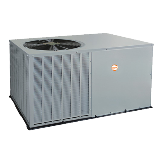
INTRODUCTION PA3Z cooling units are fully self-contained and designed for outdoor installation (See Fig. 1). As shown in Fig. 2, units are shipped in a horizontal-discharge configuration for installation on a ground-level slab. All units can be field-converted to downflow discharge configurations for rooftop applications with a field-supplied plenum. - Page 3 —3—...
-
Page 4: Inspect Shipment
Forward claim papers directly to transportation company. Manufacturer is not responsible for any damage incurred in transit. Check all items against shipping list. Immediately notify the nearest Payne Distributor if any item is missing. To prevent loss or damage, leave all parts in original packages until installation. -
Page 5: Converting Horizontal Discharge Units To Downflow (Vertical) Discharge
• Secure all ducts to building structure. Flash, weatherproof, and vibration-isolate duct openings in wall or roof according to good construction practices. Fig. 4 shows a typical duct system with PA3Z unit installed. A. CONVERTING HORIZONTAL DISCHARGE UNITS TO DOWNFLOW (VERTICAL) DISCHARGE WARNING: ELECTRICAL SHOCK HAZARD Failure to follow this warning could result in personal injury or death. -
Page 6: Install Electrical Connections
Table 2—Physical Data UNIT PA3Z OPERATING WEIGHT (lbs) COMPRESSOR TYPE Scroll Ultra Tech Scroll R-22 REFRIGERANT Charge (lb) 11.1 10.7 12.5 Accurater REFRIGERANT METERING DEVICE Orifice ID (in.) .067 .067 .082 .086 — — Orifice OD (in.) .049 .057 .059 .063... -
Page 7: Routing Power Leads Into Unit
INDOOR THERMOSTAT RETURN FROM TOP COVER POWER SOURCE POWER AND LOW-VOLTAGE DISCONNECT ENTRY PER NEC* (UNIT AND COMPOSITE ELECTRIC RUST-PROOF HEATER) BASEPAN Power Wiring CONDENSATE Control Wiring DRAIN CONNECTION Condenser Airflow *Separate disconnect per NEC (National Electrical Code) required for electric heater when single- Evaporator Airflow point conection is not used. -
Page 8: Accessory Electric Heat Wiring
Table 4—Required Subcooling REQUIRED SUBCOOLING °F (°C) Outdoor Ambient Temperature Model Size 75 (24) 82 (28) 85 (29) 95 (35) 105 (41) 17.5 (9.7) 17 (9.4) 16.5 (9.2) 16 8.9) 14 (7.8) 21 (11.7) 20.5 (11.4) 20 (11.1) 19 (10.6) 16 (8.9) Table 5—Required Liquid Line Temperature REQUIRED LIQUID LINE TEMPERATURE FOR A SPECIFIC SUBCOOLING (R-22) -
Page 9: Pre-Start-Up
HIGH-VOLTAGE POWER LOW-VOLTAGE WIRING WIRING ENTRY HOLE ENTRY HOLE A05198 Fig. 7—Unit Electrical Connection PRE-START-UP WARNING: FIRE, EXPLOSION, ELECTRICAL SHOCK HAZARD Failure to observe the following warnings could result in serious injury, death and/or property damage: 1. Follow recognized safety practices and wear protective goggles when checking or servicing refrigerant system. 2. -
Page 10: Start-Up
A05197 Fig. 8—Control Box Wiring d. Make sure that all tools and miscellaneous loose parts have been removed. START-UP Use the Start-Up Checklist supplied at the end of this book and proceed as follows: PROCEDURE 1—CHECK FOR REFRIGERANT LEAKS A. LOCATE AND REPAIR REFRIGERANT LEAKS AND CHARGE THE UNIT AS FOLLOWS: 1. -
Page 11: Low Charge Cooling
Disconnect electrical power to the unit and install lockout tag before changing blower speed. Airflow can be changed by changing the 24 volts lead connections of the blower motor. Unit PA3Z blower motors are factory wired for rated airflow operation. —11—... -
Page 12: For 208/230-V
BROWN GREEN YELLOW PINK WHITE VIOLET Thermostat Unit Control and subbase Power A05214 Fig.10B—Control Connections (Sizes 048-060) A. FOR 208/230-V BLOWER MOTORS The motor lead speed connections are as follows: SIZE RATED AIRFLOW HIGH AIRFLOW Tap 1 Tap 3 Tap 2 Tap 4 Tap 1 Tap 3... - Page 13 A05202 Fig. 11A—Typical Unit Electrical Diagram (Sizes 024-042) —13—...
- Page 14 A05203 Fig. 11B—Typical Unit Electrical Diagram (Sizes 048-060) —14—...
- Page 15 A05209 Fig. 11C—Accessory Electric Heater Wiring Table 6—Electrical Data—PA3Z VOLTAGE COMPRESSOR ELECTRIC HEAT SINGLE POINT POWER SUPPLY UNIT SIZE RANGE V-PH-HZ FUSE OR PA3Z Nominal KW* MOCP CKT BKR —/— —/— 18.6/18.6 25/25 — 3.8/5.0 18.1/20.8 41.2/44.7 30/35 — 208/230–1–60 10.9...
-
Page 16: Heating
Table 7—Dry Coil Air Delivery* Horizontal Discharge (Deduct 10 percent for 208 Volt Operation) EXTERNAL STATIC PRESSURE PA3Z SPEED TAP WATTS/C.F.M Watts C.F.M. Watts C.F.M Watts C.F.M 1108 Watts C.F.M. 1117 1053 1014 Watts C.F.M. 1344 1215 1172 1136 1095... -
Page 17: Heating Mode Charge
Table 8—Cooling Charging Chart SUCTION LINE TEMPERATURE (°F) Suction Line Pressure (PSIG) OD Temp. (°F) — — — — — — — — — — — — — — — — — — — — — — — — — —... -
Page 18: Unit Top Removal (Outdoor-Coil Side)
Replace filters with the same dimensional size and type as originally provided, when necessary. PROCEDURE 2—UNIT TOP REMOVAL (OUTDOOR-COIL SIDE) NOTE: When performing maintenance or service procedures that require removal of the unit top, be sure to perform all of the routine maintenance procedures that require top removal, including coil inspection and cleaning, and condensate drain pan inspection and cleaning. -
Page 19: Outdoor Fan
Table 9—Wet Coil Pressure Drop STANDARD CFM (S.C.F.M.) UNIT SIZE 1000 1100 1200 1300 1400 1500 1600 1700 1800 1900 2000 .027 .034 .047 .053 .036 .042 .050 .055 .063 .072 .081 .050 .055 .063 .072 .081 .090 .097 .042 .049 .052 .059... - Page 20 3.125 in. C00021 Fig. 12—Outdoor-Fan Adjustment (024–048 Size) 0.708in. C02017 Fig. 13—Outdoor-Fan Adjustment (060 Size) If oil is detected or if low cooling performance is suspected, leak-test all refrigerant tubing using an electronic leak-detector, or liquid-soap solution. If a refrigerant leak is detected, refer to Check for Refrigerant Leaks section. (See Table of Contents for page number.) If no refrigerant leaks are found and low cooling performance is suspected, refer to Refrigerant Charge.
- Page 21 Table 12—Troubleshooting—Cooling SYMPTOM CAUSE REMEDY Power Failure Call power company Loss of Charge Evaluate unit for possible refrigerant leak Switch open Fuse blown or circuit breaker tripped Replace fuse or reset circuit breaker Defective thermostat, contractor, transformer, or Compressor and outdoor fan will not start. Replace component control relay Insufficient line voltage...
- Page 22 START-UP CHECKLIST (REMOVE AND STORE IN JOB FILE) I. PRELIMINARY INFORMATION Model No ................................Serial No ................................Date ..................................Technician ................................Customer Information(Name/Address) ................................II. PRE-START-UP ____ Verify that all packing materials have been removed from unit ____ Verify that condensate connection is installed per installation instructions ____ Check all electrical connections and terminals for tightness ____ Check wire proximity to refrigerant tubes and sheet metal edges ____ Check that indoor (indoor) air filter is clean and in place...
- Page 23 —23—...
- Page 24 —24— © 2005 Payne Heating & Cooling 7310 W. Morris St., Indianapolis, IN 46231 Catalog No. IM-PA3Z-01...
Need help?
Do you have a question about the PA3Z and is the answer not in the manual?
Questions and answers