Table of Contents
Advertisement
Quick Links
Cancels:
New
II PAIZ 24-1
11/15/97
CONTENTS
Page
SAFETY
CONSIDERATIONS
......................
1 4
I. General
...................................
1
..................
5-10
..................
5
II.
...............
5
Ill.
................
5
........................
5
V.
Ductwork
..........
6
VI.
..................................
7
VII.
Connections
.........
7
.................................
11
START-UP
....................................
11 14
.................
11
Make
Adjustments
.........................
11
II1. Refrigerant
Charge
.........................
11
IV.
Adjustments
.......
14
V.
..............................
14
VI.
.....................
14
................................
14 17
..................................
16
Coil Side)
.................................
16
II1. Evaporator
Blower
and Motor
................
16
IV.
Coil,
and Condensate
Drain
Pan
..................
16
V.
............................
17
VI.
...............
17
VII.
.........................
17
VIII.
.........................
17
IX.
..........................
17
X.
........................
17
TROUBLESHOOTING
COOLING
CHART
............
18
START-UP
CHECKLIST
..........................
CL-1
NOTE TO INSTALLER
--
Before
the
installation,
READ
THESE
INSTRUCTIONS
CAREFULLY
AND COMPLETELY.
Also, make
sure
the Owner's
Manual
and
Sex-vice Instruc
tions are left with the unit after installation.
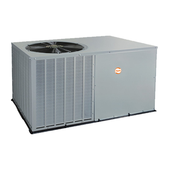
Fig. 1 -- Unit PAIZ (Size 036 Shown)
SAFETY
CONSIDERATIONS
Installation
and
servicing
of air-conditioning
equipment
can
be hazardous
due
to system
pressure
and
electrical
compo-
nents.
Only
trained
and
qualified
workers
should
install,
repair,
or service
air-conditioning
equipment.
Untrained
workers
can
perform
basic
maintenance
flmc-
tions
of cleaning
coils and
filters.
All other
operations
should
be performed
by trained
service
people.
When
working
on air-
conditioning
equipment,
pay
attention
to precautions
in the
literature,
tags
and labels
attached
to the unit,
and other
safety
precautions
that
may
apply.
Follow
all safety
codes.
Wear
safety
glasses
and
work
gloves.
Use
quenching
cloth
for
unbrazing
operations.
Have
fire
extinguisher
available
for all brazing
operations.
I. GENERAL
The
PA1Z
cooling
unit
is flflly
selficontained
and
designed
for outdoor
installation,
See Fig.
1. As shown
in Fig. 2 4, units
are
shipped
in a horizontal
discharge
configuration
fox" instal
lation
on a ground
level
slab.
All units
can be field
converted
to downflow
discharge
configurations
for rooftop
applications
with
a field-supplied
plenum.
Advertisement
Table of Contents

Related Manuals for Payne PA1Z030


Summary of Contents for Payne PA1Z030
-
Page 1: Table Of Contents
II PAIZ 24-1 Cancels: 11/15/97 CONTENTS Page SAFETY CONSIDERATIONS ...... I. General ........RECEIVING INSTALLATION ....5-10 I. Step 1 -- Check Equipment ....Step 2 -- Provide Unit Support ....Ill. Step 3 -- Provide Clearances ....IV. Step 4 -- Place Unit ...... - Page 2 REQUIRED CLEARANCES TO COMBUSTIBLE MAT'L -- mm (in.) _294 _4080 [11.51] [16.N6] Top of Unit ........Duct Side of Unit ........Side Opposite Ducts ........ Bottom of Unit ........NEC REQUIRED CLEARANCES -- mm (in.) Between Units, Power Entry Side ..... 1066.8 (42.00) Unit and Ungrounded Surfaces,...
- Page 3 REQUIRED CLEARANCES TO COMBUSTIBLE MAT'L -- mm (in.) _2940 _4080 [II,5?] [15,06] Top of Unit ........Duct Side of Unit ........£ Side Opposite Ducts ........ Bottom of Unit ........NEC REQUIRED CLEARANCES -- mm (in.) Between Units, Power Entry Side ..... 1066.8 (42.00) Unit and Ungrounded Surfaces,...
- Page 4 REQUIRED CLEARANCES TO COMBUSTIBLE MAT'L -- mm (in.) _352,r [BSR] Top of Unit ........117.B _35Z8 _537 Duct Side of Unit ........[4.B3] H3.Sfl [Lit3 Side Opposite Ducts ........ Bottom of Unit ........NEC REQUIRED CLEARANCES -- mm (in.) Between Units, Power Entry Side ..... 1066.8 (42.00) Unit and Ungrounded Surfaces, Power...
-
Page 5: Receiving And Installation
RECEIVING AND INSTALLATION III. STEP 3 -- PROVIDE CLEARANCES required minimum service clearances clearances I. STEP I--CHECK EQUIPMENT combustibles shown in Fig. 2-4. Adequate ventilation A. Identify Unit condenser must be provided. The unit model number and serial number are stamped condenser pulls through... -
Page 6: Step 5 -- Select And Install
V. STEP 5 -- SELECT AND INSTALL DUCTWORK When designing installing ductwork, consider following: The design installation of the duct system must be in accordance with: • the standards of the NFPA (National Fire Protection Association) for installation of nonresidence type air con ditioning and ventilating... -
Page 7: Step 6 -- Provide For Condensate
• Insulate and weatherproof all external ductwork. Insulate Condensate water be drained directly onto roof and cover with a vapor barrier all ductwork passing through rooftop installations (where permitted) or onto a gravel apron conditioned spaces. Follow latest Sheet Metal and Air Con ground level installations. - Page 8 Route thermostat wiresthrough grmnmet providing a drip loopatthepanel. C onnect lowvoltage leads tothethermo statasshown in Fig.13. Theunittransformer supplies 2 4-vpower f orcomplete s ys- temincluding accessory electrical heater. T ransformer is facto W wiredfor230v operation. If supply voltage is 208 v, rewire transformer primary asdescribed in theSpecial Pro cedures for208-v O peration s ection b elow.
- Page 9 Table 3 -- Electrical Data DISCONNECT NOMINAL VOLTAGE COMPRESSOR ELECTRIC HEAT POWER SUPPLY SIZE UNIT VOLTAGE RANGE PA1Z (V-Ph-Hz) Nominal kW* MOCP --/-- --/-- 16.9/ !6.9 20/ 20 16/ !6 208/230-1-60 10.9 61.0 3.8/ 5.0 18.1/20.8 25.6/ 29.0 30/ 30 24/ 27 7.5/10.0 36.1/41.7...
- Page 10 COMPRESSOR TRANSFORMER UNIT GROUND CONTACTOR GROUND -- -- LEAD -- SINGLE-PHASE LEL--- CONNECTIONS 3-PHASE TO DISCONNECT| CONNECTIONS TO DISCONNECT" PER NEC LL_- PER NEC -'-_ "BLU-- LEGEND National Electrical Code © Field Wiring © Splice Connections NOTE: Use copper wire only. Fig.
-
Page 11: Pre-Start-Up
PRE-START-UP START-UP Use the Start-Up Checklist supplied at the end of this book, and proceed as follows: I. CHECK FOR REFRIGERANT LEAKS Locate repair refrigerant leaks and charge tile unit follows: 1. Using both high and low pressure ports, locate leaks reclaim remaining... - Page 12 B. Low Charge Cooling Cooling Charging Charts, Fig. 15 20. Vary refrigerant until conditions of the appropriate chart met. Note that charging charts are different fl'om the type normally used. Charts based on charging units to the correct super- heat for the various operating...
- Page 13 IIlIll[Irillilllllji 110- IIlllll Ili_ II]lll' IIIIIII IIIIIIi IIIIIlIII]illllllll! !lllllljI' IIIl]ll]j IIILI IIIII]1]1 111111111 IIIIlII]l 111111111 Illlltl]I 111111111 Illl_ll 68_ lo I]1111[ 111111111 IIIIIII]] IIlllll IIIIIII_ jljllJ I I I I I II I I I I I_ o_621 LA"7 _ i J,,_f J...r i i .b,.P'7 I I L_...
-
Page 14: Indoor Airflow And Airflow
Airflow can be changed by changing the lead connections the blower motor, energized. NOTE: PA1Z030 and 060 units are equipped with a time- Units PA1Z024,036,048, and 060 blower motors are factory delay relay. - Page 15 Table 4 -- Dry Coil Air Delivery* -- Horizontal Discharge (Deduct 10% for 208 Volt Operation) 230 AND 460 VOLT HORIZONTAL DISCHARGE UNIT MOTOR External Static Pressure (in. wg) PA1Z SPEED DELIVERY Watts Watts 1131 !090 1038 Watts High 1391 !338 1285 !200...
-
Page 16: Air Filter
Table 7 -- Accessory Electric Heat Pressure Drop Only qualified service personnel should perform mainte- nance and service procedures that require unit top removal. (in. wg) Refer" to the following top removal procedures: HEATER 1. Remove 7 screws on unit top cover surface. -
Page 17: Condenser Fan
splash w ateronmotors, insulation, wiring, o rairfilter(s). Fox" Remove top panel to locate all the electrical controls best r esults, spray condenser coilfinsfrominside tooutside wiring. Check all electrical connections for tightness. Tighten theunit.Onunitswithanouter a ndinner condenser coil, b e suretoclean between thecoils. B esuretoflushall dirt and all screw connections. - Page 18 TROUBLESHOOTING COOLING CHART SYMPTOM CAUSE REMEDY Compressor and con- Power failure Call power company. denser fan will not Fuse btown or circuit breaker tripped Replace fuse or reset circuit breaker. start. Defective thermostat, contactor, transformer, Replace component. or control retay Insufficient line voltage Determine cause and correct.
- Page 20 START-UP CHECKLIST (Remove and Store in Job File) I. PRELIMINARY INFORMATION SERIAL NO.: MODEL NO.: TECHNICIAN: DATE: II. PRE-START-UP checkmark in box as each item is (insert completed) [] VERIFY THAT ALL PACKING MATERIALS HAVE BEEN REMOVED FROM UNIT [] VERIFY THAT CONDENSATE CONNECTION IS INSTALLED PER INSTALLATION INSTRUCTIONS [] CHECK ALL ELECTRICAL CONNECTIONS AND TERMINALS FOR TIGHTNESS...
Need help?
Do you have a question about the PA1Z030 and is the answer not in the manual?
Questions and answers