Table of Contents
Advertisement
Available languages
Available languages
INSTRUCCIONES DE OPERACIÓN Y LISTA DE PIEZAS
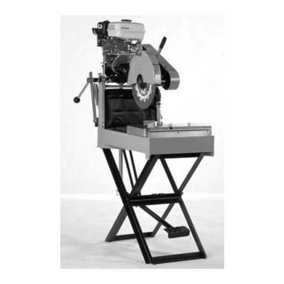
Port-A-Saw
MODEL:
Masonry / Refractory Saw
Electric & Gasoline Models
0A7738
Copyright © November, 2000 DBInc.
Printed in U.S.A.
OPERATING INSTRUCTIONS AND PARTS LIST
17400 West 119th Street
Olathe, Kansas 66061
Customer Service ............ 800-288-5040
Corp. Office ...................... 913-928-1000
Cust. Service FAX ............ 800-825-0028
Corp. Office FAX .............. 913-438-7951
Int’l. FAX ........................... 913-438-7938
Internet ........... http://www.targetdbi.com
Target Products Japan
Room 806
Taichi Roppongi Mansion
6-3-15 Roppongi
Minato-ku,Tokyo
Japan 106
Phone ................................ 03-5411-2775
FAX .................................... 03-5411-2776
Diamant Boart/Target Australia
26/7 Salisbury Road
Castle Hill, N.S.W. 2154
Australia
PHONE ............................... 02-96344677
FAX ..................................... 02-96804982
1
Advertisement
Table of Contents

Related Manuals for Target Port-A-Saw


Summary of Contents for Target Port-A-Saw
- Page 1 Customer Service .... 800-288-5040 Corp. Office ...... 913-928-1000 Cust. Service FAX .... 800-825-0028 Corp. Office FAX ....913-438-7951 Int’l. FAX ......913-438-7938 Internet ... http://www.targetdbi.com Target Products Japan Room 806 Taichi Roppongi Mansion 6-3-15 Roppongi Minato-ku,Tokyo Japan 106 Phone ........ 03-5411-2775 FAX ........
-
Page 2: Table Of Contents
EVERY MACHINE IS THOROUGHLY TESTED BEFORE LEAVING THE FACTORY. EACH MACHINE IS SUP- PLIED WITH A COPY OF THIS MANUAL. OPERATORS OF THIS EQUIPMENT MUST READ AND BE FAMIL- IAR WITH THE SAFETY WARNINGS. FAILURE TO OBEY WARNINGS MAY RESULT IN INJURY OR DEATH. FOLLOW INSTRUCTIONS STRICTLY TO ENSURE LONG SERVICE IN NORMAL OPERATION. -
Page 3: Symbol Definitions
SYMBOL DEFINITIONS DEFINICIÓN DE SIMBOLOS • Please read the instructions for use prior to operating the machine for the first time. • Antes de la puesta en marcha, lea detenidamente las instrucciones y familiaricese con la máquina. • Mandatory • Obligatorio •... - Page 4 • Motor Off • Parar El Motor • Use In Well Ventilated Area • Usar En Una Área Bien Ventilada • Do Not Use In Flammable Areas • No Usar In Áreas Inflamables • Machinery Hazard, Keep Hands And Feet Clear. •...
- Page 5 • Dangerously High Noise Level • Nivel De Ruido Elevadamente Peligroso • Pay Extreme Attention To The Care And Protection Of The Machine Before Starting Up • Ponga Extrema Atención Al Cuidado Y Preparación De La Máquina Antes De Ponerla En Marcha •...
-
Page 6: Hearing Hazard Warnings
• Number of Revolutions Per Minute, Rotational Speed • N° De Revoluciones Por Minuto, Velocidad De Rotación • Blade Flange Diameter • Diámetro De La Brida De La Hoja • Machine Mass (lbs) • Masa De La Máquina (lbs) • Engine •... -
Page 7: Decal Descriptions And Locations
DECAL DESCRIPTIONS AND LOCATIONS DESCRIPCIÓN DE CALCAMONIAS Y UBICACIONES P/N 030506 Location: Water Pan Sides (Qty. 2) All Models P/N 052130 Location: Water Pan (Qty. 2) All Models P/N 177588 Location: Blade Guard (Qty. 1) All Models P/N 169065 Location: Muffler (Qty. -
Page 8: Specifications & Power Sources
Port-A-Saw Specifications MODEL NO. PS1411 PS1421 PS1431 PS1455 TYPE 1-1/2 HP Electric 2 HP Electric 3 HP Electric 5.5 HP Gasoline Item No. (with Water Pump) M5405120S M5406120S M5407120S M50109 Blade Guard Capacity: 10 - 14" 10 - 14" 10 - 14"... -
Page 9: Saw Dimensions
Saw Dimensions GASOLINE MODEL ELECTRIC MODEL FIGURE B FIGURE A SAW DIMENSIONS ELECTRIC MODELS (Figure A) GASOLINE MODEL (Figure B) Item Length (cm) Description Item Length (cm) Description 38.2" (97.0) Saw Length (Maximum) 43.6" (110.7) Saw Length (Maximum) 19.4" (49.3) Saw Width (Maximum) 22.7"... -
Page 10: Safety Warnings - Do's And Do Not's
SAFETY FIRST! WARNINGS DO’s AND DO NOT’s WARNING: FAILURE TO COMPLY WITH THESE WARNINGS AND OPERATING INSTRUCTIONS COULD RESULT IN DEATH OR SERIOUS BODILY INJURY. read this entire operator’s manual before operating this machine. Understand all warnings, instructions, and controls. keep all guards in place and in good condition. - Page 11 SAFETY FIRST! WARNINGS DO’s AND DO NOT’s WARNING: FAILURE TO COMPLY WITH THESE WARNINGS AND OPERATING INSTRUCTIONS COULD RESULT IN DEATH OR SERIOUS BODILY INJURY. DO NOT DO NOT operate this machine unless you have read and understood this operator’s manual. DO NOT operate this machine without the blade guard, or other protective guards in place.
-
Page 12: Reference Figures: 1 - 12
FIGURES... - Page 13 FIGURES...
- Page 14 Parts Identification: A. Pan Weldment Engine Base B. Head Platform Assembly Capscrew (Blade Shaft) C. Conveyor Cart Assembly CC. Outer Flange D. Folding Stand (Optional) DD. Diamond Blade E. Skid Kit (Optional) Water Pump Belt (Gasoline Model) F. Foot Pedal Kit (Optional) Upper Spring Support G.
-
Page 15: Pre Operation Checklist
PRE OPERATION CHECKLIST Before leaving our factory, every machine is thoroughly tested. Follow our instructions strictly and your machine will give you long service in normal operating conditions. Before starting up the machine, make sure you read this entire Operation’s Manual and are familiar with the operation of the machine. -
Page 16: Instructions
operator must INDICATION MANDATORY I N F O R M AT I O N wear protective clothing INSTRUCTION appropriate to the work he is doing. PROHIBITION WARNING Any persons not involved in the work should leave the area. These signs will give advice for your safety Use only blades marked with a maximum operating speed greater than the blade shaft... -
Page 17: Check Before Operating
SMALLER than the sizes indicated in the chart shown: • Install the Lock Handle (P) onto the stud on the Left EXTENSION CORD SIZE (Minimum) Hand corner of the Head Platform Assembly (B). Tighten MOTOR 50 ft Long 75 ft Long 100 ft Long the Lock Handle (P) so that the Head Platform 115 V 230 V 115 V 230 V 115 V 230 V... -
Page 18: Fitting The Blade
CAUTION: Note that on Electric Models the Electric Models Only: • Make sure that the extension cord length is properly Capscrew (BB) has RIGHT HAND THREADS. sized for the motor used on this saw. See the chart in Installation of the wrong capscrew could Section 2 of this document. - Page 19 WARNING: Conventional “Wet” diamond 2. Hold the Hand Grip (UU) and lower the blade into blades MUST be used with water. DO NOT use the material (See Fig. 10). The blade will return to conventional “Wet” diamond blades without the upper position when force is released. water.
-
Page 20: Incidents During Operation
Incidents During Operation Gasoline Model: 1. Check engine air cleaner daily! If cutting dry check • If the engine or motor stops during sawing, check the engine air cleaner every four hours! Clean or following: replace air cleaner element as recommended by the engine manufacturer. -
Page 21: V-Belt Tension
V-Belt Tension Blade Alignment (FIGS. 11 & 12): • The blade shaft arbor on this machine is aligned at the All Models (FIGS. 5 & 6): factory so that a new blade will cut “square” with the material placed on the Cart Assembly (C). If the saw or •... -
Page 22: Accessories
• Blade flanges must be full diameter - minimum of 4" Repairs (100 mm). Replace worn flanges at once because undersized flanges shorten blade life and cause blade We carry out all repairs in the shortest possible time and at breakage. -
Page 24: Especificiones Y Fuentes De Energía
ESPECIFICACIONES MODELO NO. PS1411 PS1421 PS1431 PS1455 TIPO 1-1/2 HP, Eléctrico 2 HP, Eléctrico 3 HP, Eléctrico 5.5 HP, A Gasolina Artículo No. (con Bomba de Agua) M5405120S M5406120S M5407120S M50109 Capacidad del Protector 10 - 14" 10 - 14" 10 - 14"... -
Page 25: Dimensiones De La Sierra
DIMENSIONES DE LA SIERRA MODELOS A GASOLINA MODELOS ELECTRICOS FIGURA A FIGURA B DIMENSIONES DE LA SIERRA MODELOS ELECTRICOS (Illustración A) MODELOS A GASOLIA (Illustración B) Artículo Longitud (cm) Descripción Artículo Longitud (cm) Descripción 38,2" (97,0) Longitud de la Sierra (Máxima ) 43,6"... -
Page 26: Advertencias De Seguridad - Los Si Y Los No
¡SEGURIDAD ANTE TODO! ADVERTENCIAS HACER y NO HACER ADVERTENCIA: EL NO RESPETAR ESTAS ADVERTENCIAS E INSTRUCCIONES DE OPERACION PUEDE PROVOCAR GRAVES LESIONES O LA MUERTE. HACER Lea todo el manual antes de manejar esta máquina. Entienda todas las advertencias, instrucciones y controles. Mantenga siempre las protecciones en su lugar y en buenas condiciones. - Page 27 ¡SEGURIDAD ANTE TODO! ADVERTENCIAS HACER y NO HACER ADVERTENCIA: EL NO RESPETAR ESTAS ADVERTENCIAS E INSTRUCCIONES DE OPERACION PUEDE PROVOCAR GRAVES LESIONES O LA MUERTE. NO HACER haga funcionar esta máquina sin antes haber leído y entendido este manual. maneje esta máquina sin tener el protector de la hoja u otras protecciones instaladas en su lugar. se sitúe delante o detrás del paso de la hoja mientras el motor está...
-
Page 28: Ilustraciones De Referencia: 1 - 12
FIGURAS... - Page 29 FIGURAS...
- Page 30 Identificación de Piezas: Estructura Soldada de la Bandeja Base del Motor Conjunto de Plataforma del Cabezal Tornillo de Cabeza Plana (Eje de la Hoja) Conjunto del Carro Transportador Brida Externa Soporte Doblable (Opcional) Hoja Diamantada Equipo de Patín (Opcional) Cinta de la Bomba de Agua (Modelo a Equipo de Pedal de Pie (Opcional) Gasolina) Abrazaderas de Cojinete...
-
Page 31: Pre-Operation Checklist
LISTA DE COMPROBACIONES PREVIAS A LA OPERACION Antes de salir de la fábrica, todas las máquina son probadas extensivamente. Siga nuestras instrucciones al pie de la letra y su máquina le brindará muchos años de servicio en condiciones normales de trabajo. Lea todo este manual y familiarícese con el funcioanamiento de la máquina antes de ponerla en marcha. -
Page 32: Instrucciones
Antes de poner en marcha la máquina, INDICACION OBLIGATORIO asegúrese de leer todo este manual y INFORMACION familiarícese con el funcionamiento de esta INSTRUCCIONES máquina. El lugar de trabajo debe estar totalmente ADVERTENCIA PROHIBICION despejado, bien iluminado y totalmente libre de riesgos para la seguridad. - Page 33 • Gire las Abrazaderas de Cojinete (G) dentro de su Enchutes y Connectores del Motor Electrico posición elevada y apriete las Perillas (K) [o los Tornil- Cableado Enchute Flexible Conector los de Cabeza Plana (K), dependiendo de la fecha de Motor para del Motor...
-
Page 34: Verifique Antes De Operar
asegúrese de instalar las Arandelas Planas de Modelo a Gasolina Solamente: 1/2" (proporcionadas) en ambos costados del Brazo (L). • Monte y asegure la Palanca de Traba (P) en el Pasador de 1/2" del Soporte de Resorte Superior (FF). Apriete el Tornillo de Cabeza Plana (M) Largo de 3/8"... -
Page 35: Instrucciones De Operación
Modelos Eléctricos Solamente: Configuración en Seco: • Todos los Modelos: • Monte la Hoja Diamantada (DD): ADVERTENCIA: Las hojas diamantadas 1. Usando la Llave (LL) proporcionada (u otra que convencionales “Húmedas” DEBEN ser usadas usted tenga), afloje el Tornillo de Cabeza Plana (BB) con agua. -
Page 36: Iincidentes Durante La Operación
del regulador del motor; está fijado en fábrica para la PRECAUCION: ¡NO haga funcionar la Bomba velocidad correcta. Ver la sección “Epecificaciones” de Agua (U) por largos períodos de tiempo sin de este documento para obtener la RPM apropiada del agua! ¡La Bomba de Agua podría dañarse! motor y de la hoja. -
Page 37: Mantenimiento
la Estructura Soldada de la Bandeja (A) bajo la • Los cortes excesivamente rápidos atascarán el motor. Manguera de Drenaje de Aceite (WW) para colectar el • Si la hoja se detiene durante el corte, verifique que la aceite usado. Saque el tapón del drenaje del aceite en tensión de la cinta de transmisión es adecuada. -
Page 38: Tensión De La Cinta En V
1. Asegúrese que el Carro Transportador (C) ruede Modelo Eléctrico: libremente a lo largo de la bandeja. Si la bandeja se daña, ella debe ser reparada o reemplazada antes que • Ver “Todos los Modelos” del texto anterior. la hoja pueda ser alineada. Trabe el Conjunto de Plataforma del Cabezal (B), de manera segura, en una Modelo a Gasolina: posición horizontal. -
Page 39: Accesorios
• Haga pasar agua limpia a través de la bomba y rocíe el Reparaciones conjunto después de cada trabajo para prolongar la vida útil de la bomba y de la hoja. Nosotros efectuamos todas las reparaciones en el período • Las hojas diamantadas pueden necesitar ser “afiladas”. -
Page 40: Diagrams And Spare Parts
Diagram 1 - Upper Saw Assembly, Electric Models (19MAR98) - Page 41 Diagram 1 - PARTS LIST (23MARCH98) DIAG. PART QTY. DIAG. PART QTY. LOC. REQ. DESCRIPTION LOC. REQ. DESCRIPTION 000605 Motor & Switch, 1.5 hp 115/208-230/60/1 (A) 020572 Setscrew,Soc. Hd #10-24UNC x ½” 169422 Motor & Switch, 1.5 hp 115/60/1 (B) 030822 Wheel 000716...
- Page 42 Diagram 2 - Lower Saw Assembly, Electric Models (14jan97)
- Page 43 DIAGRAM 2 - PARTS LIST (19MARCH98) DIAG. PART QTY. DIAG. PART QTY. LOC. REQ. DESCRIPTION LOC. REQ. DESCRIPTION 177408 Pan Weldment 177401 Skid Kit (Optional) 030386 Drain Plug Assembly 177399 Skid, Wooden 030971 Clamp, Bearing, w/ Tilt Arm 020509 Capscrew, Hex 3/8-16UNC x 2” 020330 Capscrew, Hex 3/8-16UNC x 3”...
- Page 44 Diagram 3 - Upper Saw Assembly, Gasoline Model (10feb97)
- Page 45 Diagram 3 - Parts List (Rev: 23Oct2000) (Rev: 10Feb97) DIAG. PART QTY. DIAG. PART QTY. LOC. REQ. DESCRIPTION LOC. REQ. DESCRIPTION 177299 Platform Weldment 032502 (as req.) Shim, .015 " Thick 060411 Drawbolt Weldment, 3/8"-16UNC 032503 (as req.) " Shim, .020 Thick 020764 Washer, Flat 3/8...
- Page 46 Diagram 4 - Lower Saw Assembly, Gasoline Model...
- Page 47 DIAGRAM 4 - PARTS LIST (19MAR98) DIAG. PART QTY. DIAG. PART QTY. LOC. REQ. DESCRIPTION LOC. REQ. DESCRIPTION 177408 Pan Weldment 177401 Skid Kit (Optional) 030386 Drain Plug Assembly 177399 Skid, Wooden 030971 Tilt Arm Clamp 020509 Capscrew, Hex Hd., 3/8-16 x 2 020330 Capscrew, Hex Hd., 3/8-16 x 3 020743...
-
Page 48: Wiring Diagrams
Wiring Diagram: 1-1/2 HP Electric Motor Wiring Diagram: 2 HP Electric Motor... - Page 49 Wiring Diagram: 3 HP Electric Motor Wiring Diagram: 5.5 HP Honda Gasoline Engine See Honda Engine Operation Manual...
Need help?
Do you have a question about the Port-A-Saw and is the answer not in the manual?
Questions and answers