Table of Contents
Advertisement
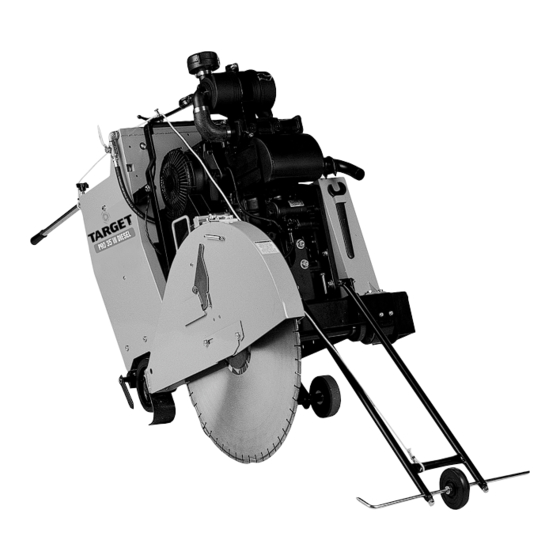
PRO 35 III DIESEL
PRO 35 III ELECTRIC
PRO 65 III DIESEL
STANDARD MODELS
0A7846
Copyright © May 2001, Diamant Boart, Inc.
Printed in U.S.A.
OPERATING INSTRUCTIONS
INSTRUCCIONES DE OPERACIÓN
17400 W. 119
th
Street
Olathe, Kansas 66061, USA
Customer Service ........ 800-288-5040
Corporate Office .......... 913-928-1000
Cust. Service Fax ........ 800-825-0028
Corporate Office Fax ... 913-438-7951
Int'l. Fax ........................ 913-438-7938
Internet ..... http://www.targetblue.com
1
Advertisement
Table of Contents

Related Manuals for Target PRO 35 III DIESEL


Summary of Contents for Target PRO 35 III DIESEL
- Page 1 OPERATING INSTRUCTIONS INSTRUCCIONES DE OPERACIÓN PRO 35 III DIESEL PRO 35 III ELECTRIC PRO 65 III DIESEL STANDARD MODELS 17400 W. 119 Street Olathe, Kansas 66061, USA Customer Service ..800-288-5040 Corporate Office ..913-928-1000 Cust. Service Fax ..800-825-0028 Corporate Office Fax ...
-
Page 2: Table Of Contents
Diagram 2 - Wiring Diagram - PRO 65 III Diesel, 182139 ..................38 Diagram 3 - Ladder Diagram - PRO 35 III Diesel and PRO 65 III Diesel, 182121 ............. 40 Diagram 4 - Wiring Diagram - PRO 35 III Electric, 182062 ..................42 Diagram 5 - PRO 35 III Electric Wiring Instructions .................... -
Page 4: Symbol Definitions
Symbol Definitions Definición De Los Simbolos • Please read the instructions for use prior to operating the machine for the first time. • Antes de la puesta en marcha, lea detenidamente las instrucciones y familiaricese con la máquina. • Mandatory •... - Page 5 • Motor Off • Parar El Motor • Use In Well Ventilated Area • Usar En Una Área Bien Ventilada • Do Not Use In Flammable Areas • No Usar In Áreas Inflamables • Machinery Hazard, Keep Hands And Feet Clear. •...
- Page 6 • Keep Work Area Clean/Well Lit, Remove All Safety Hazards • Mantenga Limpio El Sitio De Trabajo/Bien Iluminado, Elimine Todos Los Riesgos De Seguridad • Dangerously High Noise Level • Nivel De Ruido Elevadamente Peligroso • Pay Extreme Attention To The Care And Protection Of The Machine Before Starting Up •...
- Page 7 • Headlight • Luz De Cruce • Diamond Blade • Sierra Diamantada • Blade Diameter • Diámetro De La Hoja • Blade Engagement • Acoplamiento De La Hoja • Pulley Diameter • Diámetro De La Correa • Number of Revolutions Per Minute, Rotational Speed •...
- Page 8 • Electric Motor • Motor eléctrico • Engine • Motor • Engine Speed Revolutions/Minute • Velocidad Del Motor En Revoluciones Por Minuto (RPM) • Engine Start • Arranque Del Motor WARNING HEARING HAZARD DURING NORMAL USE OF THIS MACHINE, OPERATOR MAY BE EXPOSED TO A NOISE 85 dB (A) LEVEL EQUAL OR SUPERIOR TO ATENCION...
-
Page 9: Decal Descriptions And Locations
DESCRIPCIÓN DE CALCAMONIAS Y UBICACIONES DEPTH INDICATOR P/N 191308 (PRO 65 III Diesel) INSTRUMENT PANEL P/N 191009 (PRO 35 III Diesel/Electric - Shown) P/N 191028 (PRO 65 III Diesel) P/N 191006 (PRO 35 III Diesel - Shown) P/N 191127 (PRO 35 III Electric) - Page 10 REAR OF COWL P/N 191012 (All Models) LEFT AND RIGHT SIDES OF COWL (QTY 2) P/N 191001 (PRO 35 III Diesel) LEFT AND RIGHT SIDES OF COWL (QTY 2) P/N 191099 (PRO 35 III Electric) LEFT AND RIGHT SIDES OF COWL (QTY 2)
-
Page 11: Saw Dimensions
SAW DIMENSIONS ITEM DESCRIPTION - inch (mm) PRO 65III PRO 35III Height 51 (1295) 51 (1295) Minimum Saw Length 56-1/4 (1429) 52 (1321) (Handles In, Pointer Up, Guard Up) Maximum Overall Length 132-3/8 (3362) 111 (2819) (Handles Extended, Pointer Down) 30 (762) 30 (762) Handle Extension... -
Page 12: Pro 65 Iii Diesel Specifications
PRO 65 III DIESEL SPECIFICATIONS Model No: SCPL20G Standard Model: C50263 C50267 C50271 C50275 C50279 C50283 Standard w/Water Pump: C50264 C50268 C50272 C50276 C50280 C50284 STANDARD SAW FEATURES Blade Guard 18" 26" 30" 36" 48" 18" / 20" Capacity: (450mm) (650mm) (750mm) (900mm) -
Page 13: Pro 35 Iii Diesel Specifications
PRO 35 III DIESEL SPECIFICATIONS MODEL NO: Item Number: C80231 C80233 C80235 Item No. C80232 C80234 C80236 w/Water Pump: STANDARD SAW FEATURES Blade Guard 18" 26" 30" Capacity: (450mm) (650mm) (750mm) Bladeshaft RPM: 2500 1650 1650 Max. Depth Of Cut: 6-3/4"... -
Page 14: Pro 35 Iii 20Hp Electric Specifications
PRO 35 III 20HP ELECTRIC SPECIFICATIONS MODEL NO: 26S/230V 26S/460V 30S/230V 30S/460V 30S/575V Item Number: C80166 C80165 C80168 C80167 C80169 Item No. w/Water Pump: STANDARD SAW FEATURES Blade Guard Capacity: in (mm): 26" (650) 26" (650) 30" (750) 30" (750) 30"... -
Page 15: Power Source
POWER SOURCE Pro 65III Pro 35III Pro 35III E Deutz Deutz Baldor ENGINE / MOTOR: Diesel Diesel Electric Motor MODEL: BF3L1011F F2L1011F TEFC HORSEPOWER: 133 cu in 83 cu in —- DISPLACEMENT: (2.18 l) (1.37 l) 3.6" 3.6" BORE: —- (91 mm) (91 mm) 4.00"... -
Page 16: Special Instructions For Changing Blade Speed On Concrete / Asphalt Saws
Do not exceed blade shaft speed shown for each blade size. Excessive blade speed could result in blade breakage and serious personal injury. NOTE : As shown on the chart, some blade guards accept more than one size blade. PRO 35 III DIESEL ENGINE SPEED / BLADE SIZE BLADE SHAFT ENGINE SPEED... -
Page 18: Warnings
SAFETY FIRST! WARNINGS DO’s AND DO NOT’s WARNING: FAILURE TO COMPLY WITH THESE WARNINGS AND OPERATING INSTRUCTIONS COULD RESULT IN DEATH OR SERIOUS BODILY INJURY. Read this entire operator’s manual before operating this machine. Understand all warnings, instructions, and controls. keep all guards in place and in good condition. -
Page 19: Safety First
SAFETY FIRST! WARNINGS DO’s AND DO NOT’s WARNING: FAILURE TO COMPLY WITH THESE WARNINGS AND OPERATING INSTRUCTIONS COULD RESULT IN DEATH OR SERIOUS BODILY INJURY. DO NOT DO NOT operate this machine unless you have read and understood this operator’s manual. DO NOT operate this machine without the blade guard, or other protective guards in place. -
Page 20: Figures Fig. 1
FIG. 1 RAISE/LOWER SWITCH: Located on speed control lever. Use to raise and lower the saw. Push up to raise saw upward. Push down to lower the saw. SPEED CONTROL LEVER: Controls forward and reverse directions, stop, and the speed of the saw. -
Page 21: Fig. 2
FIG. 2 PRO 65 III PRO 35 III BLADE SHAFT BOLT OR NUT: Use to tighten FIG. 3 the outer flange against the diamond blade. OUTER FLANGE: Use to hold the diamond blade in position. OUTER FLANGE ARBOR: Use to support the diamond blade. -
Page 22: Fig. 4
FIG. 4 (PRO 65 III Diesel Only) JACKSHAFT CLAMPING BOLTS: Locks Jackshaft in position. BUMPER LOCKING BOLTS: Locks Idler Bumper in place. BUMPER: Reduces vibration on Idler Arm Assembly. COGGED FLAT DRIVE BELT: Drives jackshaft from engine crankshaft. JACKBOLT: Turn counterclockwise to tension v-belts. -
Page 23: Pre Operation Checklist
PRE OPERATION CHECKLIST Before leaving our factory, every machine is thoroughly tested. Follow our instructions strictly and your machine will give you long service in normal operating conditions. Before starting up the machine, make sure you read this entire Operation’s Manual and are familiar with the operation of the machine. -
Page 24: Instructions
20", 24", 26", 30", 36", 42" and 48" with Arbor Ø - 1" • Pull up on the Neutral Knob (1W). (For information, contact your Target supplier) • The saw can now be moved by standing behind it and pushing [while holding the Handle Bars (1B)]. -
Page 25: Transport (Blade Removed)
TRANSPORT (BLADE REMOVED) FITTING THE BLADE (See Fig. 1 and 2) (See Fig. 1, 2, and 3) Always set the Engine Start Switch (1L) to Turn engine off. Set Speed Control Lever the “0” (OFF) position before mounting the (1S) to STOP position. Remove diamond blade. -
Page 26: Starting The Saw
To Remove A SLIP-ON GUARD: • Move the saw forward or reverse slowly by pushing or • Using a Wrench, remove the rear retaining bolt. pulling on the Speed Control Lever (1S). Move the • Raise the Spade Safety Latch to unlatch and lift guard saw slowly to prevent stalling the blade. -
Page 27: Stopping The Saw
STOPPING THE SAW Entrust all repairs to your authorized dealer only. (See Fig. 1, 2 and 3) For EMERGENCY STOP, press down the RED ADJUSTMENTS: STRAIGHT LINE SAWING PALM SWITCH (1T) on the cowl. This will stop the engine, disconnect power to all While cutting, the saw may steer to the right from the electrical items except lights. -
Page 28: Fig. 5
BLADESHAFT V-BELT AND Lubricate every 100 hours: • Front Axle Pivot Bearings JACKSHAFT BELT TENSION Lubricate Every 250 Hours: (Pro 65 only) • Quad-Sealed Blade Shaft Bearings: Use only a (See Fig. 1, 4 and 5) Premium Lithium 12 based grease conforming to NLG1 GRADE #2 consistency. - Page 29 TensionRite™ strip lines up with the appropriate tension on Cogged Belt (4D). number for new belts • Banded V-Belts supplied by Target come with a Goodyear TensionRite™ tension gauge (4S). When Pro 65 III Diesel Tension # 3.5 retensioning belts, ALWAYS use TensionRite™ gauge to ensure achieving the proper tension.
-
Page 30: Hydraulic System
• To disengage the brake, push down on the parking brake knob (1N) . Model Used Belts New Belts Pro 35 III Diesel 26”/30” # 1.75 # 2.25 Pro 35 III Diesel 18” # 2.25 # 3.0 IMPORTANT ADVICE Pro 35 III Electric # 2.25... -
Page 31: Accessories
ACCESSORIES WARNINGS!!! BLADE GUARD CONVERSION KITS: Use the proper size blade guard for the particular diamond blade size being operated. Consult factory for turn the “ON/OFF” switch to the “0” (OFF) blade guards that are available. position prior to connecting the machine to the power source. -
Page 32: Metric Hardware
METRIC HARDWARE REPAIRS These saws are equipped with the majority of its We carry out all repairs in the shortest possible time and hardware items (capscrews, nuts, etc.) utilizing the at the most economical prices. (See front page for our METRIC system, although a limited number of hardware address and phone numbers) items continue to use the ENGLISH (INCH) system of mea-... -
Page 34: Pro 35 Iii Diesel Blade Size Conversion Chart
PRO 35 III DIESEL BLADE SIZE CONVERSION CHART Size To Convert To Size To 14"/18" 26" 30" Convert From 14"/18" No Conversion Required 176645 Wide SLIP-ON Blade Guard 166911 Wide SLIP-ON Blade Guard 18" Configured as: 183642 Pulley, 2.8” Dia 7 Gr. -
Page 35: Pro 65 Iii Diesel Blade Size Conversion Chart
PRO 65 III DIESEL BLADE SIZE CONVERSION CHART Size To Convert To Size To Convert 14"/18" 26" 30" 36" 48" From No Conversion Required 176645 Wide SLIP-ON Blade Guard 166911 Wide SLIP-ON Blade Guard 166931 Wide SLIP-ON Blade Guard 191345 14"/18"... -
Page 36: Diagram 1 - Wiring Diagram - Pro 35 Iii Diesel, 182127
Diagram 1 - Wiring Diagram - PRO 35 III Diesel, 182127... -
Page 37: Parts List
Diagram 1 - Wiring Diagram - PRO 35 III Diesel, 182127 Parts List DIAG. PART QTY. DESCRIPTION LOC. REQ. WIRING HARNESS, ENGINE (DEUTZ 4271805) 182126 WIRE HARNESS, PRO III DIESEL 163179 CABLE, BATTERY, NEGATIVE 163180 CABLE, BATTERY, POSITIVE 139261 CABLE, BATTERY, POSITIVE, HYD. -
Page 38: Diagram 2 - Wiring Diagram - Pro 65 Iii Diesel, 182139
Diagram 2 - Wiring Diagram - PRO 65 III Diesel, 182139... - Page 39 Diagram 2 - Wiring Diagram - PRO 65 III Diesel, 182139 Parts List DIAG. PART QTY. DESCRIPTION LOC. REQ. WIRING HARNESS, ENGINE (DEUTZ 4270531) 182126 WIRE HARNESS, PRO III DIESEL 163179 CABLE, BATTERY, NEGATIVE 163180 CABLE, BATTERY, POSITIVE 139261 CABLE, BATTERY, POSITIVE, HYD. 176714 CABLE, BATTERY, NEGATIVE, HYD.
-
Page 40: Diagram 3 - Ladder Diagram - Pro 35 Iii Diesel And Pro 65 Iii Diesel, 182121
Diagram 3 - Ladder Diagram - PRO 35 III Diesel and PRO 65 III Diesel, 182121... - Page 41 Diagram 3 - Ladder Diagram - PRO 35 III Diesel and PRO 65 III Diesel, 182121 Component Designators DESIGNATOR DEVICE FUNCTION ALTERNATOR BATTERY CHARGING CIRCUIT BREAKER MAIN POWER CONTROL RELAY POWER TO FUSE BLOCK CONTROL RELAY ENGINE STARTER CONTROL RELAY...
-
Page 42: Diagram 4 - Wiring Diagram - Pro 35 Iii Electric, 182062
Diagram 4 - Wiring Diagram - PRO 35 III Electric, 182062... - Page 43 Diagram 4 - Wiring Diagram - PRO 35 III Electric, 182602 Parts List DIAG. PART QTY. DESCRIPTION LOC. REQ. 176913 CABLE, CONTROL 182061 WIRING HARNESS, COWL 176914 TRANSFORMER, CURRENT 176915 STARTER, MOTOR CONTROL 176917 OVERLOAD RELAY 176838 CABLE, BATTERY, POSITIVE, HYD. 176714 CABLE, BATTERY, NEGATIVE, HYD.
-
Page 44: Diagram 5 - Pro 35 Iii Electric Wiring Instructions
Diagram 5 - PRO 35 III Electric Wiring Instructions This equipment includes the electric Motor, Motor overload protection, and Motor control circuit. For correct operation, the equipment must be selected and configured for each voltage and horsepower rating as shown in the following table. Inspection and/or changes to the equipment are to be performed only after the electrical service has been discon- nected and then by qualified personnel. -
Page 45: Diagram 6 - Ladder Diagram - Pro 35 Iii Electric, 182068
Diagram 6 - Ladder Diagram - PRO 35 III Electric, 182068... - Page 46 Target Australia, New Zealand/Dembicon Pty. Ltd Target Corporate Office 29 Kinkaid Avenue Customer Service ……….……………. 800-288-5040 North Plympton, Adelaide SA 5037 Corp. Office...………………………..913-928-1000 Australia Cust. Service FAX …………………… 800-825-0028 Phone ………………….…………..…... 61-83751000 Corp. Office FAX ..…………………..913-438-7951 FAX …………………….………….…… 61-83710990 Cust.
Need help?
Do you have a question about the PRO 35 III DIESEL and is the answer not in the manual?
Questions and answers