
Related Manuals for Mustek PowerMust 6048 Online LCD X


Summary of Contents for Mustek PowerMust 6048 Online LCD X
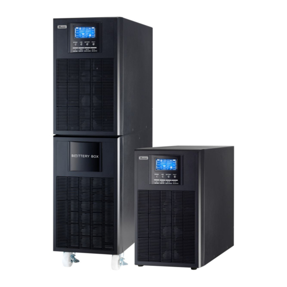
- Page 1 User Manual PowerMust 6048 Online LCD X PowerMust 10800 Online LCD X Uninterruptible Power Supply System...
- Page 2 Please comply with all warnings and operating instructions in this manual strictly. Save this manual properly and read carefully the following instructions before installing the unit. Do not operate this unit before reading through all safety information and operating instructions carefully.
-
Page 3: Table Of Contents
Table of Contents 1. SAFETY AND EMC INSTRUCTIONS ..................3 1-1. T ........................3 RANSPORTATION AND TORAGE 1-2. P ............................3 REPARATION 1-3. I ............................3 NSTALLATION 1-4. O ............................... 4 PERATION 1-5. S .............................. 4 TANDARDS 2. INSTALLATION AND OPERATION.................... 5 2-1. -
Page 4: Safety And Emc Instructions
1. Safety and EMC instructions Please read carefully the following user manual and the safety instructions before installing the unit or using the unit! 1-1. Transportation and Storage Please transport the UPS system only in the original package to protect against shock and impact. -
Page 5: Operation
1-4. Operation Do not disconnect the earth conductor cable on the UPS or the building wiring terminals in any time since this would cancel the protective earth of the UPS system and of all connected loads. The UPS system features its own, internal current source (batteries). The UPS output sockets or output terminal blocks may be electrically live even if the UPS system is not connected to the building wiring outlet. -
Page 6: Installation And Operation
2. Installation and Operation There are two different types of online UPS: standard and long-run models. Please refer to the following model table. Model Type Model Type PowerMust PowerMust 6048 Online 6048 Online LCD X L LCD X Standard Long-run model model PowerMust... -
Page 7: Single Ups Installation
Diagram 2: 6KL/10KL Rear Panel Diagram 3: 6K(L)/10K(L) Input/Output Terminal 1. External battery connector 2. RS-232 communication port 3. Intelligent slot 4. USB communication 5. Emergency power off function connector (EPO connector) 6. Cooling fan 7. Input circuit breaker 8. Input/Output terminal (Refer to Diagram 3 and 5 for the details) 9. - Page 8 Wiring spec (AWG) Model Input Output Battery Ground PowerMust 6048 Online LCD X PowerMust 6048 Online LCD X L PowerMust 10800 Online LCD X PowerMust 10800 Online LCD X L NOTE 1: The cable for 6K/6KL should be able to withstand over 50A current. It is recommended to use 10AWG or thicker wire for safety and efficiency.
-
Page 9: Software Installation
● Make sure a DC breaker or other protection device between UPS and external battery pack is installed. If not, please install it carefully. Switch off the battery breaker before installation. Warning: ● For standard battery pack, there are one DC breaker to disconnect the battery pack and the UPS. But for other external battery pack, make sure a DC breaker or other protection device between UPS and external battery pack is installed. -
Page 10: Operations
3. Operations 3-1. Button Operation Button Function Turn on the UPS: Press and hold the button more than 0.5s to turn on the UPS. ON/Enter Button Enter Key: Press this button to confirm the selection in setting menu. ... - Page 11 LCD Panel: Display Function Backup time information Indicates the backup time in numbers. H: hours, M: minutes, S: seconds Fault information Indicates that the warning and fault occurs. Indicates the fault codes, and the codes are listed in details in section 3-9. Mute operation Indicates that the UPS alarm is disabled.
-
Page 12: Audible Alarm
Battery information Indicates the Battery capacity by 0-25%, 26-50%, 51-75%, and 76-100%. Indicates the battery is fault. Indicates low battery level and low battery voltage. Input & Battery voltage information Indicates the input voltage or frequency or battery voltage. Vac: Input voltage, Vdc: battery voltage, Hz: input frequency 3-3. - Page 13 NOTE: When UPS is in Bypass mode, the output voltage will directly power from utility after you switch on the input breaker. In Bypass mode, the load is not protected by UPS. To protect your precious devices, you should turn on the UPS. Refer to next step. 2) Press and hold the “ON”...
- Page 14 some non-critical loads to disable the shutdown alarm and prolong the backup time. If there is no more load to be switched off at that time, you have to shut down all loads as soon as possible to protect the devices or save data. Otherwise, there is a risk of data loss or load failure. 2) In Battery mode, if buzzer sound annoys, users can press the Mute button to disable the buzzer.
-
Page 15: Abbreviation Meaning In Lcd Display
2) Please check the loads, wiring, ventilation, utility, battery and so on after the fault occurs. Don’t try to turn on the UPS again before solving the problems. If the problems can’t be fixed, please contact the distributor or service people immediately. For emergency case, please cut off the connection from utility, external battery, and output immediately to avoid more risk or danger. -
Page 16: Lcd Setting
3-6. LCD Setting There are three parameters to set up the UPS. Refer to following diagram. Parameter 1: It’s for program alternatives. Refer Parameter 1 to below table for the programs to set up. Parameter 2 and parameter 3 are the setting options or values for each program. - Page 17 02: Output frequency Interface Setting Parameter 2: Output Frequency 60 Hz, CVCF mode Setting the output frequency. You may choose following three options in parameter 2: 50.0Hz: The output frequency is setting for 50.0Hz. 60.0Hz: The output frequency is setting for 60.0Hz. ATO: If selected, output frequency will be decided according to the latest normal utility frequency.
- Page 18 06: reserved Interface Setting reserved 07: reserved Interface Setting reserved 08: Bypass mode setting Interface Setting Parameter 2: OPN: Bypass allowed. When selected, UPS will run at Bypass mode depending on bypass enabled/disabled setting. FBD: Bypass not allowed. When selected, it’s not allowed for running in Bypass mode under any situations.
- Page 19 11: reserved Interface Setting reserved 12: reserved Interface Setting reserved 13: Battery voltage calibration Interface Setting Parameter 2: Select “Add” or “Sub” function to calibrate battery voltage to real figure. Parameter 3: the voltage range is from 0V to 5.7V, the default value is 0V.
- Page 20 16: reserved Interface Setting reserved 17: reserved Interface Setting reserved 18: Charger maximum current setting Interface Setting Parameter 3: The maximum charging current could be adjusted. Default value is 4A for long run model and 1A for standard model. The setting range is 0.5A~6A for long run model, and 0.5A~2A for standard model Note:...
-
Page 21: Operating Mode/Status Description
3-7. Operating Mode/Status Description Operating mode/status AC mode Description When the input voltage is within acceptable range, UPS will provide pure and stable AC power to output. The UPS will also charge the battery at AC mode. LCD display CVCF mode Description When input frequency is within 46 to 64Hz, the UPS can be set at a constant output frequency, 50 Hz or 60 Hz. -
Page 22: Fault Code
LCD display Fault status Description When UPS has fault happened, it will display fault messages in LCD panel. LCD display 3-8. Fault Code Fault event Fault code Icon Fault event Fault code Icon Bus start failure None Inverter output short circuited Bus over None... -
Page 23: Trouble Shooting
4. Trouble Shooting If the UPS system does not operate correctly, please solve the problem by using the table below. Symptom Possible cause Remedy No indication and alarm in the front The AC input power is not Check if input cable firmly display panel even though the mains is connected well. -
Page 24: Storage And Maintenance
5. Storage and Maintenance 5-1. Storage Before storing, charge the UPS at least 7 hours. Store the UPS covered and upright in a cool, dry location. During storage, recharge the battery in accordance with the following table: Storage Temperature Recharge Frequency Charging Duration -25°C - 40°C Every 3 months... -
Page 25: Specifications
6. Specifications PowerMust PowerMust PowerMust 6048 PowerMust 6048 10800 Online 10800 Online MODEL Online LCD X Online LCD X L LCD X LCD X L CAPACITY* 6000 VA / 4800 W 10000 VA / 8000 W INPUT 110 ~300 VAC at 50% Load; Input Voltage Range 176~300 VACat 100% Load Frequency Range...
Need help?
Do you have a question about the PowerMust 6048 Online LCD X and is the answer not in the manual?
Questions and answers