Table of Contents
Advertisement
Quick Links
USER MANUAL
Line Interactive UPS
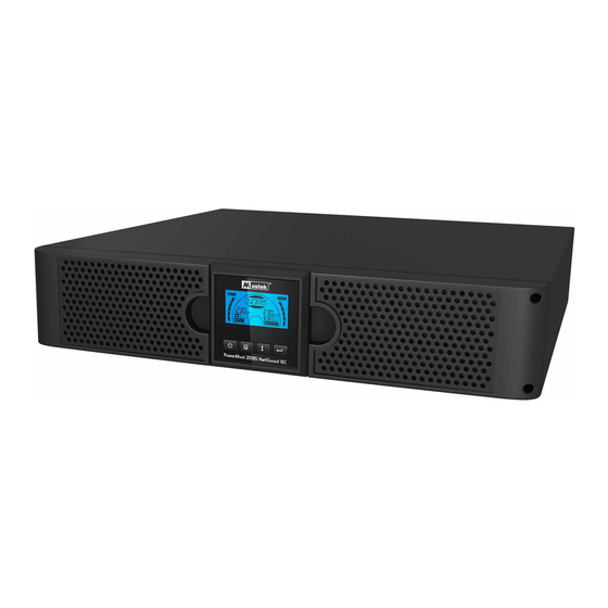
PowerMust 1513S NetGuard (1500VA), Line Int., IEC
PowerMust 2018S NetGuard (2000VA), Line Int., IEC
PowerMust 3027S NetGuard (3000VA), Line Int., IEC
IMPORTANT SAFETY INSTRUCTIONS
SAVE THESE INSTRUCTIONS
This
manual
1500VA/2000VA/3000VA series that
installation and maintenance of the UPS and batteries. Please read all
safety and operating instructions before operating the UPS. Adhere to
all warnings on the unit and in this manual. And follow all operating
and user instructions.
contains
important
instructions
should be followed during
for
Advertisement
Table of Contents

Related Manuals for Mustek PowerMust 1513S NetGuard (1500VA)


Summary of Contents for Mustek PowerMust 1513S NetGuard (1500VA)
-
Page 1: User Manual
USER MANUAL Line Interactive UPS PowerMust 1513S NetGuard (1500VA), Line Int., IEC PowerMust 2018S NetGuard (2000VA), Line Int., IEC PowerMust 3027S NetGuard (3000VA), Line Int., IEC IMPORTANT SAFETY INSTRUCTIONS SAVE THESE INSTRUCTIONS This manual contains important instructions 1500VA/2000VA/3000VA series that should be followed during installation and maintenance of the UPS and batteries. -
Page 2: Problem Solving
Warranty & Service Information Thanks for buying this Mustek UPS product. Please follow the instructions in the product manual and if applicable the software installation manual, to have the maximum use of your product. Installing the software: If you products comes with software you will find a CD Rom in the box containing the software. -
Page 3: Table Of Contents
CONTENT: USER MANUAL ·············································································· 0 1. INTRODUCTION ·········································································· 1 2. SAFETY WARNING ······································································· 1 2.1 D ······································· 2 ESCRIPTION OF OMMONLY YMBOLS 3. INSTALLATION ··········································································· 3 3.1 I ···································································· 3 NSPECTION OF 3.2 U ······························································ 3 NPACKING THE ABINET 3.3 UPS S ···············································································... -
Page 4: Introduction
1. Introduction This line-interactive series is compact and pure sine wave UPS and it is designed for essential applications and environment, such as desktops, servers, workstations, and other networking equipments. These models are available in the output ratings of 1500VA, 2000VA and 3000VA. The series protects your sensitive electronic equipments against power problems including power sags, spike, brownouts, line noise and blackouts. -
Page 5: Description Ofc
To comply with international standards and wiring regulations, the sum of the leakage currents of the UPS and the connected loads must not exceed 3.5mA. The socket outlet that supplies the UPS shall be installed near the UPS and shall be easily accessible. -
Page 6: Installation
3. Installation 3.1 Inspection of Unit Inspect the UPS upon receiving. If the UPS is apparently damaged during the shipment, please keep the box and packing material in original form for the carrier and notify the carrier and dealer immediately. 3.2 Unpacking the Cabinet To unpack the system: 1. -
Page 7: Operation
2. Assemble the rack rails with the rack-mounting. (Fig 5) Fig 4 Fig 5 3. Slide in the UPS into the rack rail and lock it in the rack enclosure. (Fig 6) 4. Tighten the screw, and the load can then be connected. (Fig 7) Fig 6 Fig 7 4. - Page 8 Control Buttons functions: Table2. Description of control button Control Switch Function Button --To turn on/off the UPS Press and hold the button more than 3 seconds. ON/OFF --To release the UPS from faulty mode Cut off input power and then press and hold the button more than 2 seconds to shut down the UPS.
- Page 9 The UPS has two groups of outlets. The output plug Output plug indicator indicator will light on if there is output power respectively. UPS status/user Strings Indicate the UPS status( see Table 4) setting display String Strings Indicate user setting options( see Table 5) Warning indication Light on when the UPS is failure or alarm.
-
Page 10: Operating Mode
User Setting String Description: The following table shows the options that can be changed by user. Table5. User Setting String [220]= 220V Output voltage mode select [230]= 230V [240]= 240V [000]= Normal range mode Input type select [001]= Wide range mode [002]= Generator mode External battery module 0~9 is the number of external battery... -
Page 11: Configuring Green
4.3.2 Select settings items: Press the Select button to select the setting items show as Table 5. 4.3.3 Enter settings item: When the LCD display “LS1” or “LS2”, press the enter button more than one second to enter the setting item and the settings string will flash. -
Page 12: Emergency Power
Table6. DB9 Female (RS232 +dry contact) PIN # Description Function Explanation BATLOW Output Battery low input Output Input Common Common (tied to chassis) Input RING Output Ring LNFAIL1 Output Line fail The connector shall be a DB-9 Female connector. (A filtered connector may be required to meet EMI requirements) RS232 Communication Port... -
Page 13: Ups Maintenance
6. UPS Maintenance 6.1 UPS and Battery Care For the best preventive maintenance, keep the area around the UPS clean and dust-free. If the atmosphere is very dusty, clean the outside of the system with a vacuum cleaner. For long battery life, keep the UPS at an ambient temperature of 25° C (77° F) 6.2 Storing the UPS and Batteries When the UPS is intended to store for a long period, recharge the battery every 6 months by connecting the UPS to utility power. -
Page 14: Replacing Ups I
6.4 Replacing UPS Internal Batteries Follow the steps and Charts as below to replace batteries: Take off the LCD box, and remove 2. Slide and Pull the front panel the screws. leftward and then take it off. 3. Disconnect the cable from the UPS 4. -
Page 15: Recycling Theu
2. Press and hold the button 10 seconds to start the battery test. The status display string shows “TEST” 6.6 Recycling the Used Battery: Never dispose the batteries in a fire. It may explode. Do not open or mutilate the batteries. Released electrolyte is harmful to the skins and eyes. -
Page 16: Rear Panels
UPS Fault LCD show red screen and “ **** ” LCD show red screen and OVLD Overload “ ” LCD show red screen and bATL Low Battery “ ” Backup Mode Sounding every 4seconds Low Battery Sounding every second Audible alarm UPS Fault Continuously Sounding Overload... -
Page 17: Trouble Shooting
2000VA/3000VA Standard) Function( AC Output Modem/Network Surge Protection SNMP Port AC Input RS232 / Dry-Contact Communication Port USB Port Earth Line Port 2000VA Standard model rear panel 3000VA Standard model rear panel 8. Trouble Shooting 8.1 Audible Alarm Trouble Shooting Indication Cause Solution... -
Page 18: Software Installation
Output Jumpers is not Check output Jumpers connected correctly UPS is on and no power to load power output Check if the LS1 and LS2 are set receptacle up from "001 to 000". Re-charge the battery at least 24 Battery is empty hours Backup time is short Battery aging...
Need help?
Do you have a question about the PowerMust 1513S NetGuard (1500VA) and is the answer not in the manual?
Questions and answers