Table of Contents
Advertisement
Advertisement
Table of Contents

Related Manuals for J2 625


Summary of Contents for J2 625
- Page 1 J2 625 Integrated Touch Screen Computer System Manual June 2012...
- Page 2 Copyright © 2012 J2 Retail Systems Ltd All rights reserved Change history Version 0.0 Release June 7, 2012 Version 0.1 Release June 15, 2012 J2 625 System Manual Version 0.1 June15, 2012 (Draft)
-
Page 3: Table Of Contents
Contents Overview ..........................6 Specifications J2 625 ......................8 J2 625 Integrated Touch Screen Computer ..............10 I/O Ports ........................10 Off / On Button ......................10 Hard Disks ........................10 Touch Screen ........................ 11 System Board ........................ 12 J2 625 Display ....................... 12 Secondary Video Port .................... - Page 4 Device Drivers ......................... 31 OPOS Drivers ........................31 J2 625 Configuration Utility ..................32 Installation ........................32 Main ..........................32 Power-On Hours ......................33 Power Cycles ........................ 33 Dim Timeout ......................... 33 Dim Brightness ......................34 Update MCU Firmware ....................35 MCU Option .........................
- Page 5 Fingerprint Reader / MSR ..................... 51 iButton / MSR ........................51 625 UPS ..........................51 RFID ..........................51 Pole Mount Options ......................51 Contact Information ....................... 52 European Office ......................52 USA Office ........................52 Australian Office ......................52 Website ......................... 52 J2 625 System Manual Version 0.1 June15, 2012 (Draft)
-
Page 6: Overview
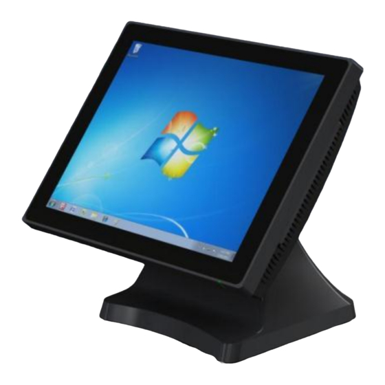
(like MSR, customer display and more) the J2 625 will perfectly satisfy most POS application requirements. The J2 625 is available with your choice of either a zero bezel resistive touch screen or a multi-touch projected capacitive touch screen. The new zero bezel five-wire resistive touch screen provides the same quick response and feel of a resistive touch screen traditionally used in the POS market. - Page 7 J2 625 System Manual Version 0.1 June15, 2012 (Draft)
-
Page 8: Specifications J2 625
Customer Display 2x20 VFD or 2x20 LCM J2 Micro UPS 30minute run time or J2 Universal UPS with 2.5 hour run time Wireless 802.11 b/g/n Mini PCI Express card with internal antennas External PoweredUSB Hub with 1 +24V, 7 +12V PoweredUSB and 6... - Page 9 LVD external adaptor UL c/us, CE, TUV, others Dust & Water IP 64 front of unit, IP 54 whole unit Power 100-240V 50-60Hz 19VDC 65 watts power supply Weight With base attached: 37x28x35cm, 14.6”x11.0”x13.8” Dimensions J2 625 System Manual Version 0.1 June15, 2012 (Draft)
-
Page 10: J2 625 Integrated Touch Screen Computer
The function of the button can be controlled by the OS. If the J2 625 hangs for some reason it can always be powered off by holding the Off /On button in for six seconds. -
Page 11: Touch Screen
Both screens are fully spill proof, dust proof, and can be cleaned with a standard glass cleaner. The J2 625 touch screen was designed to easily be changed, normally in less than two minutes. Depending on operating environment and usage, both the Resistive and PCT touch screens have strengths and weaknesses;... -
Page 12: System Board
The board can be swapped out in less than three minutes. J2 625 System board J2 625 Display The J2 625 offers 15 inch 1024 x 768 resolution display with 16.2 Million colors, CCFL backlight with 4:3 aspect ratio screen. The brightness is rated at 250cd/m . The Intel controller allows for the display to be rotated to 0, 90, 180 or 270 degrees without loss of performance. -
Page 13: Secondary Video Port
Secondary Video Port The J2 625 supports the newer digital video standard Display Port connector. This connector supports a Display Port monitor, HDMI display, DVI or VGA monitor. When used with HMDI or DVI displays, a passive adaptor cable must be used. When using a VGA display, an active adaptor is to be used. -
Page 14: Serial Ports
Serial ports The J2 625 unit has four external RS232 serial ports, all of which can supply +12V power. The serial ports use a ten pin RJ45 connector. The unit comes standard with four serial cables, three 25cm (10”) RJ45 to DB9 adapter cables, and one 152cm (5’) RJ45 to DB25 serial printer cable that works with EPSON and EPSON compatible printers. - Page 15 Pin 8 Pin 5 Pin 10 Pin 9 The J2 Cable Adaptor (supplied) RJ45 to DB25 J2 Serial Pinter Cable Pin-out when using 8 wire CAT5/6 cable RJ45-10 Pin Signal DB25 Signal RJ45- 8 Pin Signal DB25 Signal Pin 1...
-
Page 16: Usb Ports
USB Ports The J2 625 has 6 external and 3 internal USB 2.0 ports. The 6 external ports (see below) are located in the cable well with one the side of the unit for easy access. The 3 internal ports are used for different functions, such as using a PCT touch screen, Finger Print reader and/or other peripherals. -
Page 17: Power Supply
Power Input connector +12VDV Power Out The J2 625 has a fused power out connector that supplies a total of 12VDC, up to 2amp. The power supply connector is a standard notebook locking type that plugs into the system power input connector, located in the cable well, seen below... - Page 18 CD2 SOLENOID GND / STATUS CD2 The application may address the Cash Drawer port in two ways: 1) Using the J2-supplied OPOS drivers for Windows. 2) Direct access to the I/O ports Cash Drawer Controller Register The Cash Drawer Controller use one I/O address to control the Cash Drawer.
-
Page 19: Cmos Clear
CMOS Clear The J2 625 CMOS can be cleared by unplugging the system board CMOS battery for 30 seconds before plugging it back in. CMOS Battery Mini PCI-E The onboard Mini PCI Express connector is normally used for the optional internal 802.11b/g/n wireless LAN card. -
Page 20: Memory Sodimm(S)
DDR3 800/1066. Typical Power Consumption J2 625 The typical power consumption of the J2 625 is lower than a notebook computer and more comparable to a netbook computer. Using the latest generation Intel’s Atom processor and chipset allows for much lower power consumption than previous generations of POS computers. -
Page 21: Service
Service Removing the Head from the Base The 625 is shipped with a counter top base which allows for the head to be adjusted from 0-90°. To remove the integrated head from the base, fully loosen the thumbscrew located on the back of the unit under the hinge of the counter top base, as shown below. -
Page 22: Removing The Power Supply
The power supply is normally located in the counter top base. When using a wall mount bracket or the J2 UPS, the power supply would be external from the unit. To remove the power supply from the base, two screws needs to be removed as shown. -
Page 23: Vesa Mounting
VESA Mounting The 625 unit also supports the industry standard 100mm VESA mounting. The same mounting hard point used for the counter top base is used for VESA mounting. The four point that thread holes for 4mm screws. 100mm VESA Pattern... -
Page 24: Removing The Back Cover
Remove four screws where shown Carefully tilt up the back cover to remove Note: The 625 was designed so that the internals of the unit could be accessed without having to remove the mounting base or the mounting bracket of the unit. -
Page 25: Changing The System Board
Then remove the 5 screw hold the system board in place. Unplug all cables going to the system board. Remove board. (see photo below) Three screws to remove System Board J2 625 System Manual Version 0.1 June15, 2012 (Draft) -
Page 26: Adding Memory
The memory SODIMM can be installed or removed without removing the HDD cage. The J2 625 supports up to 4GB of memory in two sockets. The unit comes standard with 2GB of main memory and can support up to a maximum of 4GB. The memory type is DDR3 800/1066. -
Page 27: Bios Setting
The time and date may also be set via the operating system. System Information The J2 625 BIOS has a system information screen that displays useful system information, including the serial number of the unit. This information may also be accesed via DMI utilities. -
Page 28: Advanced Screen
These options are provided to offer maximum flexibility in configuring the J2 625. The Item Specific Help (seen on the right hand side of the screen) explains each option. -
Page 29: Power Configuration
This BIOS screen allows the enabling of the power for the serial ports, and changing the default brightness setting for the LCD screen. The LCD screen brightness can also be set via the Windows OS. J2 625 System Manual Version 0.1 June15, 2012 (Draft) -
Page 30: Security Screen
A plus and minus moves the device up or down in the list. A shift plus the number 1 enables or disables the device. A “!” will be displayed when a device is disabled in the boot list. J2 625 System Manual Version 0.1 June15, 2012 (Draft) -
Page 31: Exit Screen
UEFI BIOS came be found at the following web link. http://www.phoenix.com/pages/phoenix-securecore-tiano-tm Device Drivers All device drivers for the J2 625 can be downloaded from the J2 web site at: http://support.j2rs.com/625/ Installation instructions are included with each driver. OPOS Drivers... -
Page 32: J2 625 Configuration Utility
Installation The utility can be downloaded from the J2 web site: http://support.j2rs.com/625/utilities/ To install, simply unzip anywhere and run setup. Like other J2 utilities it can be uninstalled though the Windows control panel. Main The main screen displays the following: the current version of firmware, the power on count (in hours), a list of the number of power cycles, and the dim timeout setting and dim brightness settings. -
Page 33: Power-On Hours
Power-On Hours The MCU uses an internal timer to keep track of how many total hours the J2 625 has been up and running in its lifetime. This number shows powered-up hours only, not the powered but off/standby time. The accuracy of this timer is only about +/- 5% and is to be used as an approximate number. -
Page 34: Dim Brightness
10%. The possible range is from 5-95%, in 5% increments. Note: Dimming is important for a few reasons: one is to lower the total power consumption of the unit; another would be to prolong the LCD screen backlight LED life. J2 625 System Manual Version 0.1 June15, 2012 (Draft) -
Page 35: Update Mcu Firmware
Update MCU Firmware This tab is used to update the MCU firmware when necessary. This may be to add a new feature or function to the MSR/iButton. J2 will supply a firmware file for this when required. Use the “Select Flash Firmware File” button to start the update, as shown below. This will let you browse for the correct file. -
Page 36: Mcu Option
The utility will now update the MCU firmware. It will first write the memory then verify it. Do not turn off the J2 625 power when updating. MCU Option This tab is only used for factory programming and verification of the MCU option fuses. -
Page 37: Dimwake
XP operating system (like XP Pro, POSReady 2009, WEPOS, or XP Embedded). The DimWake program is used to take the J2 625 out of auto dim mode. The hardware can only take the system out of dimming by either a touch of the touch screen, MSR read, iButton read, or keyboard activity that changes the keyboard LED status. -
Page 38: J2 Health
J2 Health J2 has a standard program that works with all its POS products, called J2 Health. This program is used in either a standalone mode or in conjunction with J2 remote monitor/asset tracking software. The J2 Health program monitors different aspects of the POS hardware to ensure the hardware is running within specification. -
Page 39: Logging To File
As can be seen above, when running on the J2 625 the J2 Health program displays critical system voltages and system and CPU Core temperatures. For other J2 POS systems, J2 Health may display more or less information. An example would be the J2 625 unit, which in addition to the above information would also display the fan speed of the two J2 625 fans. -
Page 40: Registry Entries
J2 625 Health keys are shown below: J2 Remote Monitoring Software J2 now offers a full remote monitoring and asset tracking solution that works in conjunction with J2 Health to ensure the highest uptime possible of your POS hardware. Please contact J2 sales for more information on this fully customizable, remote monitoroption. -
Page 41: Smi Bios Info Utility
BIOS is only supported on very high end servers. Now J2 brings this feature to POS hardware. The J2 SMI BIOS Info program will run on any J2 POS hardware or for that fact on any PC hardware. It can display all DMI/SMI information on a formatted form. -
Page 42: Cash Drawer Test Utility
Cash Drawer Test Utility J2 has a generic cash drawer test utility that works on all J2 products, including the new J2 625 computer. This test program also supports the J2 625 separate status lines, such as when the special J2 625 “Y” cable is used, supporting two cash drawers. - Page 43 To use two cash drawers with the J2 625 you use a “Y” cable, either the J2 standard “Y” cable that also works with Epson printers or the special J2 625 “Y” cable that supports separate status lines (The standard cable supports shared status lines.). When using the special cable check the “Use Separate Status for Drawer2”...
-
Page 44: J2 Virtual Serial Ports Drivers
J2 Virtual Serial Ports Drivers Virtual serial ports can be used for the cash drawers, virtual 2x20 line display on the optional 10.1 LCD, Smart UPS, MSR and iButton. To open virtual serial cash drawer send a bell character to the Com port it is assigned to. -
Page 45: J2 625 Options
J2 625 Options Overview The 625 can be ordered with a 3 track MSR. This MSR is the same as used on the J2 580/615/630/680 POS systems. The MSR mounts on the right side of the 625 and uses a front facing MSR slot. -
Page 46: Installing The 625 Msr
Installing the 625 MSR The 625 MSR is installed by first removing the two rubber plugs for the option attachment point as shown below. Remove Rubber plugs Then remove the MSR cover plate on the right back side of the unit by removing the two screws, as shown. - Page 47 Attach the MSR using the two screws at the locations shown below. Mounting MSR You may now power up the 625 and the MSR should be working. For a quick test you can open Notepad and swipe a card, the information should appear in Notepad. You can now run the J2 MSR utility if you need any custom settings for the MSR.
-
Page 48: Customer Display
Customer Display Overview A 2 line by 20 character VFD or LCM customer side display is available optional for the J2 625. This customer display is the same as used on the J2 580/615/630/680 POS systems. VFD 2x20 Customer Display... -
Page 49: Secondary Video Display
Secondary Video Display The J2 625 has the same options as available on the J2 580/615/630/680 POS systems. Secondary display of 10 inch, 12 inch 4:3 and 10.1 inch 16:9 displays are available. 10 inch 4:3 Display 10.1 inch 16:9 1024x600 Display J2 625 System Manual Version 0.1 June15, 2012 (Draft) -
Page 50: Optional Wall Mount Bracket
The bracket slides on to the J2 625 mount posts, as shown. Normally the bracket would already be mounted to the wall or a VESA mount and the 625 would be hung on the bracket. Once in place the thumb screw would be tightened. -
Page 51: Fingerprint Reader / Msr
This option is the same as available on the J2 580/615/630/680 POS systems. 625 UPS Available Q3 2012 RFID Available Q3 2012 Pole Mount Options The J2 625 has the same options as available on the J2 580/615/630/680 POS systems. J2 625 System Manual Version 0.1 June15, 2012 (Draft) -
Page 52: Contact Information
J2 Retail Systems Inc. 9251 Irvine Boulevard Irvine, CA 92618 (714) 669-3111 Phone (714) 669-3133 Fax Australian Office J2 Retail Systems Pty Ltd Unit 6 83/85 Boundary Road Mortdale NSW 2223 Australia 02 9584 5222 Phone 02 9584 1500 Fax Website http://www.j2retailsystems.com...
Need help?
Do you have a question about the 625 and is the answer not in the manual?
Questions and answers