Table of Contents
Advertisement
Quick Links
Advertisement
Table of Contents

Related Manuals for J2 580


Summary of Contents for J2 580
- Page 1 J2 580 Integrated Touchscreen Computer System Manual May 2008...
-
Page 2: Table Of Contents
Adding / Upgrading SDRAM ..................16 Removing the Power Supply Adaptor ................16 Jumper Settings ....................... 17 580 Motherboard ......................17 Cash Drawer........................24 BIOS Settings ........................27 Starting the BIOS Setup ....................27 ... -
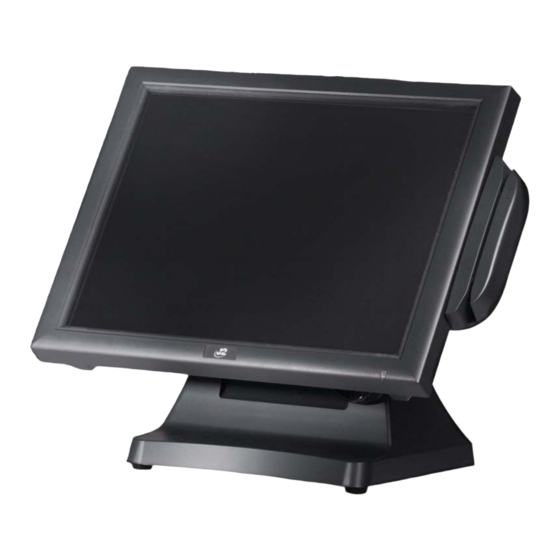
Page 3: Overview
10 seconds! The HDD is easily accessible as it too is housed on a removable tray. The footprint of the J2 580 is particularly compact making it ideal for the space conscious retailer. -
Page 4: Specification
LAN (10 / 100) 1, RJ45 in cable well (Realtek RTL8139) 1 supports standard VGA monitor or optional 12” or 10.4” secondary customer side display, powered from 580 Cash Drawer 1 x RJ 11 (24V or 12V) with status DC Jack 1 Power in, 19VDC 4.75 amps... - Page 5 20% ~ 85% RH non condensing Humidity Dimensions 370x250x340mm (W x D x H) Weight 7.45kg Windows XP, WEPOS, XP Embedded, Windows CE 5.0, Linux OS Support * This specification is subject to change without prior notice. 580 System Manual Version 1.0 May 31, 2008...
-
Page 6: Packing List
The following contents should be found in the carton: Standard Items 2: COM Cables (3) 1: System 3: Printer Cables 4: Wall mount / VESA adapter Not pictured 5: Screws for VESA Mount (4) 6: COM port cable labels 580 System Manual Version 1.0 May 31, 2008... -
Page 7: System View
System View Front View Card reader Rear View Ventilation Module I/O Ports OFF/ON BUTTON 580 System Manual Version 1.0 May 31, 2008... -
Page 8: I/O View
I/O View OFF/ON BUTTON COM 1, 2, 3, 4 Line out Line in Parallel Cash Drawer DC-IN 580 System Manual Version 1.0 May 31, 2008... -
Page 9: Optional Items
Optional Items Power Supply Bracket Hinge bracket MSR module (front swipe) iButton / iButton-MSR combo Finger Print / MSR-Finger Print Combo Secondary Display 12” (also 10.4” available) 2X20 Character Customer Display 580 System Manual Version 1.0 May 31, 2008... -
Page 10: System Installation
System Installation Counter Top Base The 580 is shipped with a counter top base. This base allow for the head to be adjust from 0-90°. To remove the integrated head from the base loosen the thumbscrew located on the back of the unit under the hinge of the counter top base as shown below. - Page 11 To mount the 580 to the base do the reverse as shown below. a. attach the panel to the desk mount hinge bracket and slide it into the position as shown by the arrows b. Tighten the thumbscrew to finish the installation 580 System Manual Version 1.0 May 31, 2008...
-
Page 12: Vesa / Wall Mount Bracket Installation
The bracket slides on to the 580 mount posts as shown. Normally the bracket would already be mounted to the wall or a VESA mount and the 580 would be hung on the bracket. Once in place the thumbscrew would be tightened. -
Page 13: Msr Installation
Connect the cable and tighten the screw c. Slide the MSR into the position and tighten the screw to finish the installation. Be careful not to pitch the cable when installing. 580 System Manual Version 1.0 May 31, 2008... -
Page 14: Hard Drive Access
Hard Drive Access Loosen the screw Slide the Hard Module as shown 580 System Manual Version 1.0 May 31, 2008... -
Page 15: Replacing The Mother Board
Replacing the Mother Board Loosen the two thumbscrews (you may require a screw driver) Pull the handle in the direction as shown order to release the mainboard tray from the system 580 System Manual Version 1.0 May 31, 2008... -
Page 16: Adding / Upgrading Sdram
Note: There are two memory socket, one one each side of the mother board. Population order does not matter. Removing the Power Supply Adaptor Remove the two screws to release the adaptor and the bracket from the system. 580 System Manual Version 1.0 May 31, 2008... -
Page 17: Jumper Settings
Jumper Settings 580 Motherboard 580 System Manual Version 1.0 May 31, 2008... - Page 18 Change the JP8 jumper setting from N/C to 1-2. Wait 2 seconds. Change the JP8 jumper setting back to N/C. Reinstall mother board. Apply power and continue. Power Mode Setting Function ◎N/C ATX Power (use for 580) AT Power 580 System Manual Version 1.0 May 31, 2008...
- Page 19 1024 Dual SHORT SHORT OPEN OPEN 1024 x 768 Single SHORT OPEN SHORT SHORT x 600 Single SHORT OPEN SHORT OPEN * This is the setting required for the 580 system 580 System Manual Version 1.0 May 31, 2008...
- Page 20 Pin 6 DSR# Pin 7 RTS# Pin 8 CTS# Pin 9 Pin 10 CN15: CPU FAN Connector Pin 1 Pin 2 Feedback Pin 3 CN18: USB 2 Pin 1 +5V_USB1 Pin 2 USB20_R_P1 580 System Manual Version 1.0 May 31, 2008...
- Page 21 Pin 1 Pin 2 Pin 3 KDATA_SIO_TO_MSR Pin 4 KDATA_SIO_TO_MSR Pin 5 KDATA_MSR_TO_GFINGER Pin 6 KCLK_MSR_TO_GHINGER Pin 7 RS232_6_RX# Pin 8 RS232_6_TX# Pin 9 RS232_6_CTS# Pin 10 RS232_6_RTS# Pin 11 KB_EN Pin 12 580 System Manual Version 1.0 May 31, 2008...
- Page 22 Pin 3 Pin 6 Pin 4 Pin 2 Pin 5 Pin 7 Pin 6 Pin 3 Pin 7 Pin 8 Pin 8 Pin 4 Pin 9 Pin 5 Pin 10 Pin 9 580 System Manual Version 1.0 May 31, 2008...
- Page 23 CRT_R Pin 3 Pin 4 CRT_G Pin 5 Pin 6 CRT_B Pin 7 Pin 8 CRT_HSYNC Pin 9 Pin 10 CRT_VSYNC JP2: VGA Power Pin 1 Pin 2 Pin 3 Pin 4 580 System Manual Version 1.0 May 31, 2008...
-
Page 24: Cash Drawer
You can install a cash drawer through the cash drawer port. Please verify the pin assignment before installation. Cash Drawer Pin Assignment Signal CD 1 SOLENOID STATUS 12V / 24V CD 2 SOLENOID Cash Drawer Voltage Jumper 24V JUMPER 12V JUMPER 580 System Manual Version 1.0 May 31, 2008... - Page 25 Bit 1: Cash Drawer “DOUT bit1” pin output control. = 1: Opening the Cash Drawer = 0: Allow closing the Cash Drawer Bit 0: Reserved Note: Please follow the Cash Drawer control signal design to control the Cash Drawer. 580 System Manual Version 1.0 May 31, 2008...
- Page 26 Do not fire longer the 100ms. OPOS and Virtual Serial Port Cash Drawer drivers are available from J2 for the 580. 580 System Manual Version 1.0 May 31, 2008...
-
Page 27: Bios Settings
The time and date can also be set though the keys to select items and the Enter key to OS. The total memory installed in the system can accept and enter the sub-menu. be seen on this screen as well. 580 System Manual Version 1.0 May 31, 2008... - Page 28 This screen shows the current Health readings on be set in this menu. The “PWRON After the 580. A Windows based program is available PWR-Fail” controls weather the unit will turn from J2 that can access and display the same back on by itself after AC power is lost.
-
Page 29: Driver Installation
Driver Installation Driver Download If you did not purchase your operating system from J2 you may download the drivers for the 580 system from the J2 web site http://www.j2retailsystems.com/support/580/. For Windows XP there are 5 drivers that need to be installed. They are:... - Page 30 Click the “Yes” button on the License d. Click the ”Next” button on the Readme Agreement window. Information window. e. Click the “Finish” button and restart your system. 580 System Manual Version 1.0 May 31, 2008...
-
Page 31: Vga Driver Installation
Click the “Next” button on the Welcome Computer window. window. c. Click the ”Next” button on the Welcome d. Click the ”Yes” button on the License window. Agreement window. e. Click the ”Finish” button and restart your system. 580 System Manual Version 1.0 May 31, 2008... -
Page 32: Postouch Driver Installation
Click the ”Next” button on the “Choose Agreement” window. Destination Location” window. e. Click the “Next” button on the “Select f. Click the “Finish” button on the “Install Program Folder” window. Shield Wizard Complete” window. 580 System Manual Version 1.0 May 31, 2008... - Page 33 The serial ports are scanned for a touch “Programs TouchUtility Scan RS232 device. Touch Device”. k. Select “Programs TouchUtility Touch l. Click “Scale / Offset” on the POSTouch Utility”. Utility window. 580 System Manual Version 1.0 May 31, 2008...
- Page 34 Select “Device 9Pts Calibration” on the three point calibration of the touch panel. POSTouch Utility window. o. Follow the instructions on the screen to do a nine point calibration of the touch panel. 580 System Manual Version 1.0 May 31, 2008...
-
Page 35: 10/100Mb Lan Driver Installation
Additional drivers and utilities such as OPOS drivers, MSR program utility, 802.11g WIFI card drivers, cash drawer test utility, POS heath monitor software and others can be down loaded from J2 web site (link below). Please see the documentation and help files supplied with these drivers and utilities for more information. -
Page 36: Customer Display Option
Customer Display Option How to enable power and connect the cable for a 580 customer display Slacken the two holding screws & slide the main board out of the unit. Enable 12V for Com3 or Com4. The Photo shows Com4 enabled Cable must be fitted correctly. The end with the shrink sleeve goes into the display, the other end to COM3 or COM4 580 System Manual Version 1.0 May 31, 2008... -
Page 37: Dip Switch And Software Setting
Command Control SW12 Function ON Depend on SW1~SW11 setting Bypass SW1~SW11 setting, fixed at: Command type: POS7300, Baud rate: 9600 Parity check: None-parity Demo mode: Disable International char set: USA, standard Europe 580 System Manual Version 1.0 May 31, 2008... - Page 38 Windows-1251 (Cyrillic) 21 OFF ON OFF ON ON U.S.A Windows-1252 22 ON OFF OFF ON ON U.S.A Windows-1255 (Hebrew) 23 OFF OFF OFF ON ON U.S.A Windows-1257 (Baltic) 580 System Manual Version 1.0 May 31, 2008...
Need help?
Do you have a question about the 580 and is the answer not in the manual?
Questions and answers