Table of Contents
Advertisement
Quick Links
Advertisement
Table of Contents

Related Manuals for J2 680


Summary of Contents for J2 680
- Page 1 J2 680 Integrated Touchscreen Computer System Manual May 2012...
- Page 2 Copyright © 2011-2012 J2 Retail Systems Ltd All rights reserved Change history Version 1.0 Release May 11, 2012 J2 680 System Manual Version 1.0 May 11, 2012...
-
Page 3: Table Of Contents
Versatility ........................11 System ..........................12 Configurations ....................... 12 Processor Support ......................12 Processors currently supported on the 680 ..............13 I/O Ports ........................14 Off / On Button ......................14 Hard Disks ........................15 Zero Bezel Touch Screen ....................15 System Board ........................ - Page 4 Installation ........................55 Operations ........................55 Cash Drawer Test Utility ....................56 Installation ........................56 Operation ........................56 J2 Virtual Serial Ports Drivers ..................57 RAID ..........................58 RAID Overview ......................58 AHCI ..........................58 Enabling RAID in the BIOS ..................59 RAID Volume Creation ....................
- Page 5 Packing List ........................63 Standard Items ......................63 680 Optional Peripherals ....................64 MSR ..........................64 Overview ........................64 Installing the 680 MSR ....................65 Customer Display ......................67 Overview ........................67 Secondary Video Display ....................67 Fingerprint Reader / MSR ..................... 68 iButton / MSR ........................
-
Page 6: Overview
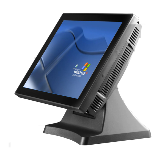
The J2 680 is the second generation of very high performance integrated Point of Sale computer from J2. Built on the features and capabilities for the J2 650 the J2 680 offers even higher performance and expanded I/O. The J2 680 retains all the versatility of... - Page 7 J2 680 System Manual Version 1.0 May 11, 2012...
-
Page 8: Specification
Power In 19VDC 9.47 amps One headset, one microphone-in Audio Jack Printer Power +24 V 2.5 amps, supports most 24V POS printers Power LED Front bezel, green for on, amber for standby J2 680 System Manual Version 1.0 May 11, 2012... - Page 9 (W x D x H) Weight 8.1kg Windows 7, POSReady 7, Windows 7 Embedded, XP, OS Support POSReady 2009, XP Embedded, version of Linux * This specification is subject to change without prior notice. J2 680 System Manual Version 1.0 May 11, 2012...
-
Page 10: Features
Hot Swappable RAID/ Dual Hard Drives Like the J2 650, the first integrated POS system on the market to offer a hot swappable RAID feature the J2 680 also supports this feature. The two internal 2.5 inch SATA hard drives can be configured as a RAID array which gives true fault tolerance to the hard drive subsystem. -
Page 11: Ups
680. The combination of all the 680 unique features allows for the 680 to fit many roles. The 680 is not just one product, but a full product range all in one system. From fan less thin client to Quad Core RAID Server - the 680 does it all. -
Page 12: System
J2 680 could be configured with a quad core i5 or i7 processor. J2 will be happy to help you determine what you may require from the 680 in the most cost effective way. More memory may be added to get the performance needed, or sometimes a quad core processor and dual HDD with RAID are needed. -
Page 13: Processors Currently Supported On The 680
2: Processor with blue shading are available but may requires a minimum order quantity. 3: All processor shown above should work on the J2 680 but are not necessarily tested. 4: "7 Year" = support from Intel to J2 for 7 years, same as embedded products. -
Page 14: I/O Ports
The function of the button can be controlled by the OS. If the 680 hangs for some reason it can always be powered off by holding the Off / On button in for six seconds. -
Page 15: Hard Disks
A carrying tray (two of which are supplied with the 680) fits onto a new drive without tools. The drive can now easily be slid into the drive bay. In a RAID 1 configuration a drive can be hot swapped, removed, or inserted with the power on (see section on RAID setup). -
Page 16: System Board
BIOS or controlled by a utility supplied by J2. Secondary Video Port(s) A standard PC VGA video port is supported on the 680 and can be set as the primary or secondary display The VGA video port has an industry standard HD DB15 connector. - Page 17 The 680 also supports the newer digital video standard DisplayPort connector. This connector supports a DisplayPort monitor or a HDMI display or DVI monitor. When used with HMDI or DVI display a passive adapter cable is used. When used with a HDMI display Audio is support via the same HMDI cable.
-
Page 18: Serial Ports
A BIOS setting is used to enable the voltage on each port. J2 does not normally recommend using the +5 volt option on COM 1 and is only there for some legacy devices. The problem is it easy for +5 volt device to be plugged into a +12 enable serial port by mistake which will burn out the +5 volt device. -
Page 19: Poweredusb Ports
USB Ports The 680 has six external and 4 internal USB 2.0 ports. Of the six external ports (see below) five ports are located in the cable well and one is located on the left side of the unit for easy access. The four internal USB ports are as follows: one can be used for the optional Finger Print Reader and is located on the MSR connecting point. -
Page 20: Kensington Security Slot
Ethernet Connector Kensington Security Slot There is a Kensington Security Slot (lock slot) on the 680. (Please see below). It is located on the head in the cable well. The Kensington locks are normally used as a deterrent to prevent opportunistic theft. Most retail locks will work with the 680, however please check to see if a lock fits, as not all do. -
Page 21: Audio
The 680 uses the VIA1708B HD audio controller. There is one internal speaker. Both a microphone jack and a headset jack are located in the cable well of the 680, as seen below, which allows for the connection of a microphone and headset or audio out to other devices. -
Page 22: Cash Drawer Port
Cash Drawer Port The 680 is equipped with one Cash Drawer port that will support one or two drawers. This port is located in the cable well and uses the industry standard RJ-11 connector and pin out (illustrated below). This pin-out is the same as used by EPSON printers and cables for the EPSON printer normally work with the 680. - Page 23 Cash Drawer 2 fire Reserved Cash Drawer 1 status Reserved The “Y” cable used to support two cash drawers on the one RJ-11 is the same as is used on Epson printers. J2 680 System Manual Version 1.0 May 11, 2012...
-
Page 24: Cmos Clear
The 680 CMOS can be cleared jumping JP3 pin 1-2 then removing the jumper. Power Supply The 680 uses a notebook type power supply that is normally mounted in the base of the unit. The power supply is rated with an output of 180 watts 19 VDC 9.47 Amps and has an input rating of 100-240VAC at 50~60Hz 2.5Amps maximum. -
Page 25: Typical Power Consumption 680
Typical Power Consumption 680 The typical power consumption of the 680 is lower that most desktop computers. Using the latest generation on Intel’s Desktop processors and chipset allows for much lower power consumption than previous generations of POS computer. This when coupled with proper system configuration can greatly reduce the systems total carbon foot print. -
Page 26: Service
Service Removing the Head from the Base The 680 is shipped with a counter top base which allows for the head to be adjusted from 0-90°. To remove the integrated head from the base, fully loosen the thumbscrew located on the back of the unit under the hinge of the counter top base, as shown below. -
Page 27: Removing The Power Supply
The power supply is normally located in the counter top base. When using a wall mount bracket or the J2 UPS, the power supply would be external from the unit. To remove the power supply from the base, three screws needs to be removed as shown. -
Page 28: Vesa Mounting
VESA Mounting The 680 unit also supports the industry standard 100mm VESA mounting. The same mounting hard point used for the counter top base is used for VESA mounting. The four point that thread holes for 4mm screws. 100mm VESA Pattern... -
Page 29: Optional Wall Mount Bracket Installation
The bracket slides on to the J2 680 mount posts, as shown. Normally the bracket would already be mounted to the wall or a VESA mount and the 680 would be hung on the bracket. Once in place the thumb screw would be tightened. -
Page 30: Removing The Back Cover
Remove four screws where shown Carefully tilt up the back cover to remove Note: The 680 was designed so that the internals of the unit could be accessed without having to remove the mounting base or the mounting bracket of the unit. -
Page 31: Changing The System Board
First remove the back cover. There are 3 screws that hold the system board in place that will need to be removed. (see photo below) Three screws to remove System Board J2 680 System Manual Version 1.0 May 11, 2012... - Page 32 While using the I/O bracket to pull on, slide the board out towards the bottom of the unit as shown. When reinstalling the system board make sure the locking tabs on the bottom of the board lock into their mating slots. J2 680 System Manual Version 1.0 May 11, 2012...
-
Page 33: Adding Memory
Remove the back cover. You can now access the two memory sockets, the order in which the memory is populated does not matter. The J2 680 supports up to 16GB of memory in two sockets. Memory type is 240 DIMM DDR3 1066/1333. -
Page 34: Accessing The Hdd/Sdd Drives
No physical damage will happen to the HDD if inserted or removed with power on. J2 680 System Manual Version 1.0 May 11, 2012... -
Page 35: Bios Setup
BIOS Setup Entering the BIOS Setup To enter the BIOS Setup, turn on or reboot the 680 and press the DEL key after the BIOS sign-on screen appears. The main menu of the BIOS setup will be displayed, this can take a few seconds. -
Page 36: Advanced Settings
When enabled, a message screen will appear and Shift-F10 can be typed to access the PXE ROM options. This option is located on the “Advanced” tab as shown above. J2 680 System Manual Version 1.0 May 11, 2012... -
Page 37: Sata Configuration
IDE compatible mode and default BIOS setting. The other two selections are RAID and AHCI modes. Please see the separate section in the manual for RAID Setup for further information on using RAID and AHCI modes. SATA Configuration Screen J2 680 System Manual Version 1.0 May 11, 2012... -
Page 38: Peripheral Power And Lcd Brightness Configuration
Peripheral Power and LCD Brightness Configuration This submenu allows for the enabling of power for the serial ports, default cash drawer pulse timing and default LCD brightness level and power for a J2 supplied VGA port monitor. Power enable for serial Ports... -
Page 39: Power Configure Screen
Wake on LAN is enabled by default but can be disabled in this screen. RTC Configuration The RTC has an alarm function that can be used to turn the 680 on at a preset time of day. This function is enabled by this setting. The wake up time can also be set here. -
Page 40: Boot Settings
If more than one bootable device is in the system the boot order can be set in this menu. If a bootable USB storage device is plugged in at boot up the 680 will boot from that device by default. If this is not desired the boot order can be changed here. A list of detected drives will be displayed with the current boot order. -
Page 41: Exit Options
BIOS changes. It is not necessary to exit setup from this screen. To discard any BIOS setup changes you can type the ESC key from any screen to exit. Exit Options Screen J2 680 System Manual Version 1.0 May 11, 2012... -
Page 42: Driver Installation, Windows
Driver Installation, Windows Chipset Driver Installation The chipset driver is needed to get the full potential from the 680 chipset. It should be loaded before other drivers and first thing after booting. The drivers can be downloaded from the J2 web site: http://www.j2retailsystems.com/support/680/Chipset/. -
Page 43: Audio Driver Installation
Audio Driver Installation The Audio Drivers can be downloaded from the J2 web site at: http://www.j2retailsystems.com/support/680/Audio/. After extracting the driver to a temporary folder, run Setup, and then follow the instructions below: First Audio setup screen Just click on Next to install the Audio driver. -
Page 44: Lan Driver Installation
LAN Driver Installation The LAN drivers can be downloaded from the J2 web site: http://www.j2retailsystems.com/support/680/LAN/. After extracting the driver to a temporary folder, run Setup. Just answer Next or Yes to all the screen prompts and the driver will install. - Page 45 Resistive Touch Screen Driver Installation The Touch Drivers can be downloaded from the J2 web site at: http://www.j2retailsystems.com/support/680/Touch/. When run, the diver will display a welcome screen, at this point just press next for the next few screens. When you get to this screen check both RS232 and USB options and click next.
- Page 46 Click finish at the screen. The driver will then detect the port the touch screen is on (normally COM6) then ask you to reboot the system. After rebooting the touch should be working. Calibration is not needed as this is done at the factory. J2 680 System Manual Version 1.0 May 11, 2012...
-
Page 47: Multi-Touch Projected Capacitive Touch Driver
The first page of options allows for the change how your finger or stylus interacts with the screen. The sensitivity and function of touch to the screen can be changed here. J2 680 System Manual Version 1.0 May 11, 2012... - Page 48 The other four option tabs are shown below for reference. They are self-explanatory in most case and additional information can be obtained through the Windows help function. J2 680 System Manual Version 1.0 May 11, 2012...
-
Page 49: Optional Multi-Touch Projected Capacitive Touch Driver
A copy of the current version can also be found on J2’s web page support page for the 680. The “General” tab has the utility to set the monitor map when using multiple touch monitors. - Page 50 The “Display” tab controls how multiple touch monitors are used if required. The Hardware tab display the current controller firmware version and a “Hardware Calibration” function that will reset the screen calibration back to factory values. J2 680 System Manual Version 1.0 May 11, 2012...
-
Page 51: Opos Drivers
OPOS drivers The OPOS driver for the 680 supports the Cash Drawer ports, the optional MSR, the optional 2x20 character Customer Display, and the optional iButton reader. The OPOS driver may be downloaded from the J2 web site at: http://www.j2retailsystems.com/support/680/. -
Page 52: J2 Health
J2 Health J2 has a standard program that works with all its POS products, called J2 Health. This program is used in either a standalone mode or in conjunction with J2 remote monitor/asset tracking software. The J2 Health program monitors different aspects of the POS hardware to ensure the hardware is running within specification. -
Page 53: Logging To File
As can be seen above, when running on the J2 680 the J2 Health program displays critical system voltages and system and CPU Core temperatures. For other J2 POS systems, J2 Health may display more or less information. An example would be the J2 680 unit, which in addition to the above information would also display the fan speed of the two J2 680 fans. -
Page 54: Registry Entries
J2 680 Health keys are shown below: J2 Remote Monitoring Software J2 now offers a full remote monitoring and asset tracking solution that works in conjunction with J2 Health to ensure the highest uptime possible of your POS hardware. Please contact J2 sales for more information on this fully customizable, remote monitor solution. -
Page 55: Smi Bios Info Utility
BIOS is only supported on very high end servers. Now J2 brings this feature to POS hardware. The J2 SMI BIOS Info program will run on any J2 POS hardware or for that fact on any PC hardware. It can display all DMI/SMI information on a formatted form. -
Page 56: Cash Drawer Test Utility
Direct I/O Port 48c” setting to test the cash drawer(s). (see example below) The “Use Comm Port 10 & 11” option is to test the cash drawer you set up using the J2 virtual serial ports program. The virtual serial port program must be installed with the cash drawer virtual serial ports set to Comm 10 &... -
Page 57: J2 Virtual Serial Ports Drivers
J2 Virtual Serial Ports Drivers Virtual serial ports can be used for the cash drawers, virtual 2x20 line display on the optional 10.1 LCD, Smart UPS, MSR and iButton. To open virtual serial cash drawer send a bell character to the Com port it is assigned too. -
Page 58: Raid
RAID array are striped. With striping, data is split between two drives. This allows the 680 to read the data more than twice as fast as with a single drive. The performance can be more than twice as fast because the Intel RAID driver also uses the AHCI NCQ function built into the SATA drives. -
Page 59: Enabling Raid In The Bios
Enabling RAID in the BIOS The Intel manual for the Intel Matrix Storage Manager covers this same information given below in more detail and can be downloaded from the J2 web site. The documentation below is tailored for the 680 only. -
Page 60: Installing The Intel Matrix Storage Manager Software
4. After pressing Enter, you should be presented with a list of available SCSI Adapters. Select your controller from the list. The 680 uses the ICH8R driver. 5. The next screen should confirm your selected controller. Press the Enter key again to continue. - Page 61 Power to the system does not need to be turned off, and the system will still operate. First remove the bad drive. After removing the bad drive insert the hot spare into the 680. In the Intel Matrix Storage Manager select Advance Mode, and under the Action tab select “Rescan for Plug and Play Devices”.
- Page 62 The RAID has now mirrored the drive and the system is now protected for a drive failure. Note: Please refer to J2’s “Using RAID in a Point of Sale Environment” white paper for more information on using the 680 RAID function. (Available September 2008) J2 680 System Manual Version 1.0 May 11, 2012...
-
Page 63: Packing List
Packing List In addition to the foam packing inserts, the following contents should be found in the 680 shipping carton. Standard Items 1: System with Power Supply and AC cord 2: Cable Well Cover 3: Printer Power Port Cable : COM Port Colored Coded Cable Labels J2 680 System Manual Version 1.0 May 11, 2012... -
Page 64: 680 Optional Peripherals
680 Optional Peripherals Overview The 680 can be ordered with a 3 track MSR. This MSR is the same as used on the J2 580/615/625/630 POS systems. The MSR mounts on the right side of the 680 and uses a front facing MSR slot. -
Page 65: Installing The 680 Msr
Installing the 680 MSR The 680 MSR is installed by first removing the two rubber plugs for the option attachment point as shown below. Remove Rubber plugs Then remove the MSR cover plate on the right back side of the unit by removing the two screws, as shown. - Page 66 Attach the MSR using the two screws at the locations shown below. Mounting MSR You may now power up the 680 and the MSR should be working. For a quick test you can open Notepad and swipe a card, the information should appear in Notepad. You can now run the J2 MSR utility if you need any custom settings for the MSR.
-
Page 67: Customer Display
Customer Display Overview A 2 line by 20 character VFD customer side display is available optional for the J2 680. This customer display is the same as used on the J2 580/615/625/630 POS systems. Secondary Video Display The J2 680 has the same options as available on the J2 580/615/625/630 POS systems. -
Page 68: Fingerprint Reader / Msr
This option is the same as available on the J2 580/615/625/630 POS systems. This bracket can be uses when not using a VESA mount. Pole Mount Options The J2 680 has the same options as available on the J2 580/615/625/630 POS systems. J2 680 System Manual Version 1.0 May 11, 2012... - Page 69 J2 Retail Systems Inc. 9251 Irvine Boulevard Irvine CA 92618 (714) 669-3111 Phone (714) 669-3133 Fax Australian Office J2 Retail Systems Pty Ltd Unit 6 83/85 Boundary Road Mortdale NSW 2223 Australia 02 9584 5222 Phone 02 9584 1500 Fax Web site http://www.j2retailsystems.com...
Need help?
Do you have a question about the 680 and is the answer not in the manual?
Questions and answers