Table of Contents
Advertisement
Advertisement
Table of Contents

Related Manuals for J2 225


Summary of Contents for J2 225
- Page 1 J2 225 Integrated Touch Screen Computer System Manual April 2012...
- Page 2 Copyright © 2012 J2 Retail Systems Ltd All rights reserved Change history Version 1.0 Release May 29, 2012 J2 225 System Manual Version 1.0 May 29, 2012...
-
Page 3: Table Of Contents
Contents Overview ..........................6 Design Concept J2 225 ...................... 8 Specifications J2 225 ......................9 J2 225 Integrated Touch Screen Computer ..............10 I/O Ports ........................10 Off / On Button ......................10 Hard Disks ........................11 Touch Screen ........................ 11 System Board ........................ - Page 4 Installation ........................51 Operation ........................51 J2 Virtual Serial Ports Drivers ..................53 J2 225 Options ......................... 54 J2 225 LCM 2x20 Character Customer Display ............54 Installation ........................55 J2 225 LCM Configuration Utility ................57 Installation ........................57 J2 225 MSR ........................
- Page 5 J2 225 Wall Mount / Counter-top Mount Kit .............. 66 Packing list ........................66 Assembly ........................67 J2 225 10.1 inch 1024 x 600 LCD Customer Display ........... 71 Installation ........................72 Contact Information ....................... 75 European Office ......................75 USA Office ........................
-
Page 6: Overview
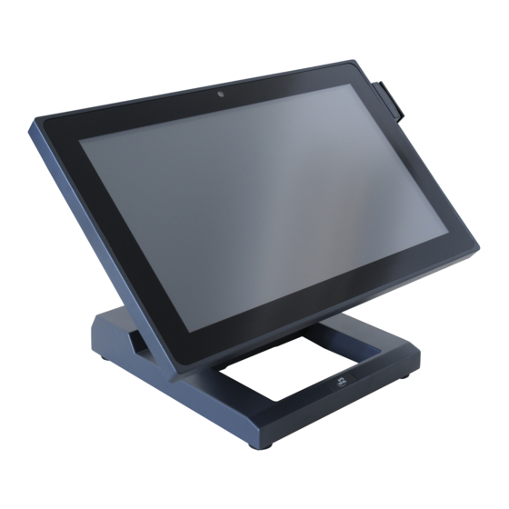
J2 225 will perfectly satisfy most POS application requirements, while looking sleek and elegant in any setting. The J2 225 is available with your choice of either a zero bezel resistive touch screen or a multi-touch projected capacitive touch screen. The new zero bezel five-wire resistive touch screen provides the same quick response and feel of a resistive touch screen traditionally used in the POS market. - Page 7 The J2 225 supports the standard Microsoft operating systems: Windows 7, POSReady 7, Windows 7 Embedded, XP, POSReady 2009 and XP embedded, as well as the soon-to- be-released Windows 8. The J2 225 is equally proficient with the many flavors of Linux. J2 225 System Manual...
-
Page 8: Design Concept J2 225
The shipping box for the J2 225 is no bigger than the size of an average notebook shipping box, which is also about 1/3 to 1/4 the size and weight of other POS products. -
Page 9: Specifications J2 225
Digital Persona module, attached to front bottom of display head Customer Display J2 225 2x20 customer display, Serial Secondary Video 10 inch 1024x600 16:9 J2 225 Secondary Display internal connection Wireless 802.11 b/g/n Mini PCI Express card with internal antennaes Environmental Operating Temp. -
Page 10: J2 225 Integrated Touch Screen Computer
The function of the button can be controlled by the OS. If the J2 225 hangs for some reason it can always be powered off by holding the Off /On button in for six seconds. -
Page 11: Hard Disks
One 2.5 inch SATA hard drive (HDD) or a solid state drive (SSD) are standard with the J2 225. The SATA interface can support data transfer rates up to 3.0 GB/s. The J2 225 offers standard either a 160GB HDD or 16GB SSD, but can be ordered with other size HDD or SSD as well. -
Page 12: System Board
J2 225 System board J2 225 Display The J2 225 offers a 1366 x 768 resolution display with 16.2 Million colors, and a 14 inch LED backlight with 16:9 aspect ratio screen. The brightness is rated at 220cd/m . The Intel controller allows for the display to be rotated to 0, 90, 180 or 270 degrees without loss of performance. -
Page 13: Secondary Video Port
The secondary video displays can be configured as Twin, Intel Dual Display Clone, or Extended Desktop. Most all monitor resolutions from 640 x 480, up to 2560 x 1600 are supported. When the internal secondary J2 225 video display is used the secondary video port is not available. DisplayPort Video Port J2 225 System Manual Version 1.0 May 29, 2012... -
Page 14: Serial Ports
Serial ports The J2 225 unit has four external RS232 serial ports, all of which can supply +12V power. The serial ports use a ten pin RJ45 connector. The unit comes standard with four serial cables, three 38cm (15”) RJ45 to DB9 adapter cables, and one 152cm (5’) RJ45 to DB25 serial printer cable that works with EPSON and EPSON compatible printers. - Page 15 Pin 8 Pin 5 Pin 10 Pin 9 The J2 Cable Adaptor (supplied) RJ45 to DB25 J2 Serial Pinter Cable Pin-out when using 8 wire CAT5/6 cable RJ45-10 Pin Signal DB25 Signal RJ45- 8 Pin Signal DB25 Signal Pin 1...
-
Page 16: Usb Ports
USB Ports The J2 225 has 4 external and 4 internal USB 2.0 ports. The 4 external ports (see below) are located in the cable well. The 4 internal ports are used for different functions, such as using a PCT touch screen, RFID reader and/or other peripherals. -
Page 17: Audio
The J2 225 uses the VIA1708B HD audio controller. There is one internal speaker. A combo microphone jack and headset jack are located in the cable well of the J2 225, as seen below, which allows for the connection of a microphone and headset, or audio out to other devices. - Page 18 CD2 SOLENOID GND / STATUS CD2 The application may address the Cash Drawer port in two ways: 1) Using the J2-supplied OPOS drivers for Windows. 2) Direct access to the I/O ports Cash Drawer Controller Register The Cash Drawer Controller use one I/O address to control the Cash Drawer.
-
Page 19: Cmos Clear
CMOS Clear The J2 225 CMOS can be cleared by unplugging the system board CMOS battery for 30 seconds before plugging it back in. CMOS Battery Mini PCI-E The onboard Mini PCI Express connector is normally used for the optional internal 802.11b/g/n wireless LAN card. -
Page 20: Memory Sodimm(S)
DDR3 800/1066. Power Supply The J2 225 uses a notebook-type power supply that is mounted in the base of the unit. The power supply is rated with an output of 65 watts 18.5 VDC 3.5 Amps, and has an input rating of 100-240VAC at 50~60Hz 1.7Amps maximum. -
Page 21: 12Vdv Power Out
+12VDV Power Out The J2 225 has a fused power out connector that supplies a total of 12VDC, up to 2amp. The power supply connector is a standard notebook locking type that plugs into the system power input connector, located in the cable well, seen below... -
Page 22: Service
The J2 225 swing arm base can be folded down flat for shipping, or it can also be used with the wall mounting option. Being able to fold flat greatly reduces the size of the shipping box, thereby reducing its shipping cost and storage space. -
Page 23: Removing The Power Supply
It does act as a holder for the power supply, which can be removed if the base is not needed. When not using the base, the VESA 75mm mounting points may be used to mount the J2 225. The power supply is mounted in the base, and there are two posts to store the extra DC power cord, shown below. -
Page 24: Cable Routing
Use a coin, finger or screw driver to remove cable cover Remove cable cover so cable can be routed J2 225 System Manual Version 1.0 May 29, 2012... - Page 25 Route cables Replace cover J2 225 System Manual Version 1.0 May 29, 2012...
-
Page 26: Vesa Mounting
Cables can route out via the rear of unit or through a hole in the counter top VESA Mounting The J2 225 unit also supports the industry standard 75mm VESA mounting. The same mounting hard point used for the swing arm base is used for VESA mounting. The four points have holes threaded for the 4mm screws. -
Page 27: J2 225 Disassembly Instructions
J2 225 Disassembly Instructions You will need a Philips screwdriver and a small coin to disassemble the J2 225. Step 1: Power down the unit and unplug all cables on the I/O panel. Step 2: Remove the HDD/SSD from the system by removing the securing screw and slide it out. - Page 28 Step 4: Remove the four screws, shown below, that secure the back cover. J2 225 System Manual Version 1.0 May 29, 2012...
- Page 29 Step 5: Unclip the outer bezel from the unit by pulling gently on the edge of the front of the unit. J2 225 System Manual Version 1.0 May 29, 2012...
- Page 30 Step 6: Using a small coin (this works best) at the pry point between the front bezel and back cover, slip the coin in to pry the back cover off. J2 225 System Manual Version 1.0 May 29, 2012...
- Page 31 The touch screen or LCD panel can now be removed by detaching the touch screen cable and removing the four screws, as shown below. Carefully unplug the LCD panel when removing. J2 225 System Manual Version 1.0 May 29, 2012...
- Page 32 Electronics Removal: The J2 225 electronics can be removed by first unplugging the 5-wire cable attached to the board, then removing the five screws, as shown. The board will need to be moved gently from side to side to release it from the somewhat sticky thermal pads.
-
Page 33: Bios Setting
The time and date may also be set via the operating system. System Information The J2 225 BIOS has a system information screen that displays useful system information, including the serial number of the unit. This information may also be accesed via DMI utilities. -
Page 34: Advanced Screen
These options are provided to offer maximum flexibility in configuring the J2 225. The Item Specific Help (seen on the right hand side of the screen) explains each option. -
Page 35: Power Configuration
This BIOS screen allows the enabling of the power for the serial ports, and changing the default brightness setting for the LCD screen. The LCD screen brightness can also be set via the Windows OS. J2 225 System Manual Version 1.0 May 29, 2012... -
Page 36: Security Screen
A plus and minus moves the device up or down in the list. A shift plus the number 1 enables or disables the device. A “!” will be displayed when a device is disabled in the boot list. J2 225 System Manual Version 1.0 May 29, 2012... -
Page 37: Exit Screen
UEFI BIOS came be found at the following web link. http://www.phoenix.com/pages/phoenix-securecore-tiano-tm Device Drivers All device drivers for the J2 225 can be downloaded from the J2 web site at: http://support.j2rs.com/225/ Installation instructions are included with each driver. OPOS Drivers... -
Page 38: J2 225 Configuration Utility
Installation The utility can be downloaded from the J2 web site: http://support.j2rs.com/225/utilities/ To install, simply unzip anywhere and run setup. Like other J2 utilities it can be uninstalled though the Windows control panel. Main The main screen displays the following: the current version of firmware, the power on count (in hours), a list of the number of power cycles, and the dim timeout setting and dim brightness settings. -
Page 39: Power-On Hours
Power-On Hours The MCU uses an internal timer to keep track of how many total hours the J2 225 has been up and running in its lifetime. This number shows powered-up hours only, not the powered but off/standby time. The accuracy of this timer is only about +/- 5% and is to be used as an approximate number. -
Page 40: Dim Brightness
10%. The possible range is from 5-95%, in 5% increments. Note: Dimming is important for a few reasons: one is to lower the total power consumption of the unit; another would be to prolong the LCD screen backlight LED life. J2 225 System Manual Version 1.0 May 29, 2012... -
Page 41: Basic Msr Settings
MSR/iButton MCU. The “Load Defaults and Save to MSR” button loads the default settings for the MSR/iButton and auto dimming functions. J2 225 System Manual Version 1.0 May 29, 2012... -
Page 42: Advanced Msr/Ibutton Settings
When preamble or postamble data needs to be edited, a touch-friendly onscreen keyboard is displayed. The data may be entered by the onscreen keyboard or by an attached keyboard. The onscreen keyboards shown below are for uppercase, lower case and control characters. J2 225 System Manual Version 1.0 May 29, 2012... - Page 43 J2 225 System Manual Version 1.0 May 29, 2012...
-
Page 44: Update Mcu Firmware
Update MCU Firmware This tab is used to update the MCU firmware when necessary. This may be to add a new feature or function to the MSR/iButton. J2 will supply a firmware file for this when required. Use the “Select Flash Firmware File” button to start the update, as shown below. This will let you browse for the correct file. -
Page 45: Mcu Option
The utility will now update the MCU firmware. It will first write the memory then verify it. Do not turn off the J2 225 power when updating. MCU Option This tab is only used for factory programming and verification of the MCU option fuses. -
Page 46: Dimwake
XP operating system (like XP Pro, POSReady 2009, WEPOS, or XP Embedded). The DimWake program is used to take the J2 225 out of auto dim mode. The hardware can only take the system out of dimming by either a touch of the touch screen, MSR read, iButton read, or keyboard activity that changes the keyboard LED status. -
Page 47: J2 Health
J2 Health J2 has a standard program that works with all its POS products, called J2 Health. This program is used in either a standalone mode or in conjunction with J2 remote monitor/asset tracking software. The J2 Health program monitors different aspects of the POS hardware to ensure the hardware is running within specification. -
Page 48: Logging To File
As can be seen above, when running on the J2 225 the J2 Health program displays critical system voltages and system and CPU Core temperatures. For other J2 POS systems, J2 Health may display more or less information. An example would be the J2 680 unit, which in addition to the above information would also display the fan speed of the two J2 680 fans. -
Page 49: Registry Entries
J2 225 Health keys are shown below: J2 Remote Monitoring Software J2 now offers a full remote monitoring and asset tracking solution that works in conjunction with J2 Health to ensure the highest uptime possible of your POS hardware. Please contact J2 sales for more information on this fully customizable, remote monitoroption. -
Page 50: Smi Bios Info Utility
BIOS is only supported on very high end servers. Now J2 brings this feature to POS hardware. The J2 SMI BIOS Info program will run on any J2 POS hardware or for that fact on any PC hardware. It can display all DMI/SMI information on a formatted form. -
Page 51: Cash Drawer Test Utility
Cash Drawer Test Utility J2 has a generic cash drawer test utility that works on all J2 products, including the new J2 225 computer. This test program also supports the J2 225 separate status lines, such as when the special J2 225 “Y” cable is used, supporting two cash drawers. - Page 52 To use two cash drawers with the J2 225 you use a “Y” cable, either the J2 standard “Y” cable that also works with Epson printers or the special J2 225 “Y” cable that supports separate status lines (The standard cable supports shared status lines.). When using the special cable check the “Use Separate Status for Drawer2”...
-
Page 53: J2 Virtual Serial Ports Drivers
J2 Virtual Serial Ports Drivers Virtual serial ports can be used for the cash drawers, virtual 2x20 line display on the optional 10.1 LCD, Smart UPS, MSR and iButton. To open virtual serial cash drawer send a bell character to the Com port it is assigned to. -
Page 54: J2 225 Options
J2 225 Options J2 225 LCM 2x20 Character Customer Display The J2 225 supports an optional two line by twenty character mono color liquid crystal display module (LCM). This LCM display shows black characters on a white background for maximum visibility to the customer. The LCM supports a number of firmware emulations of popular customer displays which allows existing POS software to run without modification. -
Page 55: Installation
Installation The J2 225 LCM can be installed in just a minute. To install: first power down the system, then remove the secondary display mounting cover (as shown below): J2 225 System Manual Version 1.0 May 29, 2012... - Page 56 This cable provides power and serial data to the LCM module. Once the cable is plugged in, feed any extra cable into the unit and attach the LCM with the two 4mm screws provided with the display. J2 225 System Manual Version 1.0 May 29, 2012...
-
Page 57: J2 225 Lcm Configuration Utility
Installation The utility can be downloaded from the J2 web site: http://support.j2rs.com/Utilities/ To install just unzip anywhere and run setup. Like other J2 utilities it can be uninstalled through the Windows control panel. J2 225 System Manual Version 1.0 May 29, 2012... - Page 58 By default the LCM is mapped to ComPort 6, 9600 baud and N-8-1 parity. The emulation, character set, baud rate and parity can be changed under CD Settings. J2 225 System Manual Version 1.0 May 29, 2012...
- Page 59 The LCM firmware can be updated using the “Program CD Firmware” tab. J2 will supply the necessary file should a firmware update be required. J2 225 System Manual Version 1.0 May 29, 2012...
-
Page 60: J2 225 Msr
The MSR is a Keyboard Wedge device with all data being sent to the keyboard port. For software that requires a serial port MSR, the J2 Virtual Serial Port driver can be used to allow the J2 225 MSR to function as a serial port MSR. J2 225 System Manual... -
Page 61: Installation
Installation The J2 225 MSR can be installed in just a minute. To install, first power down the system. Then remove the option mounting point cover, as shown below: J2 225 System Manual Version 1.0 May 29, 2012... - Page 62 This completes the installation of the J2 225 optional MSR. Note that the MSR can be mounted to any one of the J2 225 option mounting points. By default the internal MSR cable is routed to the upper right hand corner of the unit, however this cable can be rerouted if need be to use any of the other three option mounting points.
-
Page 63: J2 225 Ibutton Reader
Keyboard Wedge device with all data being sent to the keyboard port. For software that requires a serial port iButton reader, the J2 Virtual Serial Port driver can be used to allow the J2 225 iButton reader to function as a serial port iButton reader. J2 225 System Manual... -
Page 64: Installation
Installation The J2 225 iButton reader can be installed in just a minute. To install, first power down the system, then remove the option mounting point cover, as shown below: Plug in the ibutton cable as shown:. J2 225 System Manual... - Page 65 Note that the iButton reader can be mounted to any one of the J2 225 mounting option points. By default the internal iButton reader cable is routed to the upper right hand corner of the 225, but this cable can be rerouted if need be to use any of the other three option mounting points.
-
Page 66: J2 225 Wall Mount / Counter-Top Mount Kit
J2 225 Wall Mount / Counter-top Mount Kit The J2 225 has available an optional kit for wall mounting the unit when not using the VESA mounts. This kit has the advantage that it works together with the J2 225 standard base to allow the viewing angle and distance from the wall to be adjusted. -
Page 67: Assembly
Be sure to use a mounting screw with sufficient hold force for the material being mounted to and allow for the stress of the adjustment of the swing arm base. J2 225 System Manual Version 1.0 May 29, 2012... - Page 68 Next the J2 225 can be hung on the bracket by sliding the unit down on the bracket so it catches on all four mounting clips, as illustrated below. This will need to be done by feel, of course, as you will not be able to see the clips engage.
- Page 69 The unit is now secure enough and the swing base can be adjusted to the desired viewing angle. Rubber Screw Cover Safety Screw Location J2 225 System Manual Version 1.0 May 29, 2012...
- Page 70 Some possible viewing angles using the wall mount bracket. J2 225 System Manual Version 1.0 May 29, 2012...
-
Page 71: J2 225 10.1 Inch 1024 X 600 Lcd Customer Display
J2 225 10.1 inch 1024 x 600 LCD Customer Display The J2 225 supports an optional customer side LCD display. This display attaches to an internal DisplayPort via short cable that support power and data to the display. The display resolution is 1024 x 600 16:9. This display is the same type as used as on many Netbook computers. -
Page 72: Installation
Installation The J2 225 10.1 display can be installed in just a minute. To install: first power down the system, then remove the secondary display mounting cover (as shown below): J2 225 System Manual Version 1.0 May 29, 2012... - Page 73 This cable provides power and video data to the 10.1” display. Once the cable is plugged in, feed any extra cable into the unit and attach the LCM with the two 4mm screws provided with the display. J2 225 System Manual Version 1.0 May 29, 2012...
- Page 74 10.1 display electroins. J2 also supplies a virtual serial port 2 x 20 line customer driver that works with the 10.1” display. This allows part of the screen to display data that would normal be used on a 2 x 20 display while using the rest of the display for advertising content.
-
Page 75: Contact Information
J2 Retail Systems Inc. 9251 Irvine Boulevard Irvine, CA 92618 (714) 669-3111 Phone (714) 669-3133 Fax Australian Office J2 Retail Systems Pty Ltd Unit 6 83/85 Boundary Road Mortdale NSW 2223 Australia 02 9584 5222 Phone 02 9584 1500 Fax Website http://www.j2retailsystems.com...
Need help?
Do you have a question about the 225 and is the answer not in the manual?
Questions and answers