MINN KOTA Riptide ST User Manual
Bowmount copilot control autopilot saltwater trolling motors
Hide thumbs
Also See for Riptide ST:
- User manual (40 pages) ,
- User manual (26 pages) ,
- User manual (4 pages)
Table of Contents
Advertisement
:
NoTe
do NoT reTUrN YoUr miNN KoTa moTor To YoUr
. Y
reTailer
oUr reTailer is NoT aUTHoriZed To rePair
. Y
or rePlaCe THis UNiT
oU maY oBTaiN serViCe BY
•
: 1-800-227-6433
CalliNG miNN KoTa aT
•
reTUrNiNG YoUr moTor To THe miNN KoTa FaCTorY
;
serViCe CeNTer
•
seNdiNG or TaKiNG YoUr moTor To aNY miNN KoTa
aUTHoriZed serViCe CeNTer oN eNClosed lisT
Please iNClUde ProoF oF PUrCHase
aNd PUrCHase daTe For WarraNTY serViCe WiTH aNY
.
oF THe aBoVe oPTioNs
PLEaSE ThOROUGhLY REaD ThIS USER MaNU-
aL. fOLLOW aLL INSTRUCTIONS aND hEED aLL
SafETY & CaUTIONaRY NOTICES BELOW. USE Of
ThIS MOTOR IS ONLY PERMITTED fOR PERSONS
ThaT haVE REaD aND UNDERSTOOD ThESE USER
INSTRUCTIONS. MINORS MaY USE ThIS MOTOR ONLY
UNDER aDULT SUPERVISION.
serial NUmBer
PUrCHase daTe
User Manual for
:
.
,
serial NUmBer
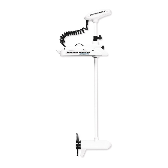
RIPTIDE ST
Riptide ST
pg. 2-3
pg. 4
pg. 5
pg. 6
pg. 7
pg. 7
pg. 8
pg. 8
pg. 9
pg. 9
pg. 10
pg. 11
pg. 11
pg. 11
Bowmount
Copilot Control
Autopilot
Saltwater
Trolling Motors
CoPilot
pg 12
pg. 12
pg. 13
pg. 13
pg. 14
pg. 14-15
pg. 15
pg. 15
pg. 16
pg. 17
Advertisement
Table of Contents
Troubleshooting

Related Manuals for MINN KOTA Riptide ST


Summary of Contents for MINN KOTA Riptide ST
-
Page 1: Table Of Contents
RIPTIDE ST User Manual for Bowmount Copilot Control Autopilot Saltwater NoTe do NoT reTUrN YoUr miNN KoTa moTor To YoUr reTailer oUr reTailer is NoT aUTHoriZed To rePair Trolling Motors or rePlaCe THis UNiT oU maY oBTaiN serViCe BY •... -
Page 2: Features
SYSTEM COMPONENTS COPILOT RIPTIDE ST REMOTE High Speed Bypass Decrease Speed AutoPilot ON/OFF Steer Left Increase Speed Steer Right Prop ON/OFF COPILOT RIPTIDE ST RECEIVER Preinstalled in sideplate Learn Button Side Plate Cover Preinstalled Specifications subject to change without notice. - Page 3 Depth / Drive Collar Fall away motor ramps Factory installed CoPilot Maximizer / Permanently Sealed Electronics Wireless remote Lifetime Warranty Flexible Composite Shaft Cool Running Permanent Magnet Motor Weedless Wedge Propeller Auto Pilot Indicator functional on equipped motors only Push Button Battery Gauge System Ready Indicator Tilt Lock Lever Allows Easy Retraction To Storage Position...
-
Page 4: Installation
INSTaLLaTION Of ThE RIPTIDE ST: We recommend that you have another person help with this procedure. Tools required: 7/16” wrench, #3 phillips screw- driver and electric drill with a 9/32” bit. 1. Remove the four sideplate screws. Remove the right sideplate and swing the left sideplate out and away from the base extrusion. -
Page 5: Cautions
attention: •Avoid running your motor with the propeller outside of the water. This may result in injuries from the rotat- ing propeller. •It is recommended to set the speed selector to zero and place the motor in the deployed position prior to connecting power cables. -
Page 6: Operation
GENERaL: System Ready (green): The motor is equipped with a system ready indicator. Indicator light will be on when motor is deployed and power is applied to the motor. When the motor is properly stowed the indicator light will go off indicating all power has been turned off to the motor. -
Page 7: Controls
aUTOPILOT™ CONTROLS: AUTOPILOT ON EQUIPPED MOTORS ONLY The MINNKOTA AutoPilot uses a magnetic compass and a microprocessor chip to keep the trolling motor pointed in the direction you want to go. Each time the wind or water current moves the boat off course, the AutoPilot senses the change and steers itself back to the original heading. -
Page 8: Battery Information
This would immediately lead to a short and utmost fire danger. Recommendation: Use battery boxes and covered battery terminal clamps like Minn Kota accessory #MK-BC-1. The motor is equipped with a battery gauge. This LED gauge provides an accurate display of the remaining charge in the battery. -
Page 9: Battery Connections
BaTTERY CONNECTION 12 Volt Systems: a. Connect a connector cable to positive (+) terminal of battery 1. Make sure that the motor is switched off (speed selector on “0”). 1 and to negative (–) terminal of battery 2. 2. Connect positive (+) red lead to positive (+) battery terminal. b. -
Page 10: Wiring Diagram
ThIS IS a UNIVERSaL MULTI-VOLTaGE DIaGRaM. DOUBLE ChECk YOUR MOTORS VOLTaGE fOR PROPER CONNECTIONS Over-Current Protection Devices not shown in illustrations. CONTROL BOARD/ CARTE DE COMMANDE ACCESSORY PLUG STEERING MOTOR BATTERY GAUGE WHITE BLACK COMPASS BLACK ACCESSORY PLUG BLACK M- AUTOPILOT INDICATOR, RED RED M+ SYSTEM READY INDICATOR, GREEN... -
Page 11: Propeller Replacement
The following specifications are for general guidelines only: CAUTION: These guidelines apply to general rigging to support your Minn Kota Motor. Powering multiple motors or additional electrical devices from the same power circuit may impact the recommended conductor gauge and circuit breaker size. If you are using wire longer than that provided with your unit, follow the conductor gauge and circuit breaker sizing table below. -
Page 12: Feature Information
: Avertissement : Ces directives s'appliquent au gréement générale à l'appui de votre moteur Minn Kota. Alimenter plusieurs moteurs ou des dispositifs électriques supplémentaires depuis le même circuit de puissance peut influencer la taille recommandée de la jauge du conducteur et disjoncteur. Si vous utilisez fil plus long que celui fourni avec votre unité, suivre le conducteur jauge et le disjoncteur dimensionnement... -
Page 13: Troubleshooting
AUTHORIZED SERVICE CENTERS Minn Kota has over 300 authorized service centers in the United States and Canada where you can purchase parts or get your products repaired. Please visit www.minnkotamotors.com and click on “Service Center Locator” under the “Service” tab to locate a service center in your area. -
Page 15: Troubleshooting
RT80/ST This page provides MinnKota® WEEE compliance disassembly instructions. For more information about where you should dispose of your waste equipment for recycling and 80 LBS ThRUST recovery and/or your European Union member state requirements, please contact your 24 VOLT dealer or distributor from which your product was purchased. -
Page 16: Faq's, Fcc Disclaimer
Please use the correct part numbers from the parts model serial list. Payment for any parts ordered from the MINN KOTA parts department, may be by cash, personal check, Discover Card, MasterCard or VISA. To order, call 1-800-227-6433 or FAX 1-800-527-4464. Item... -
Page 17: Limited Warranty
Fuera de los Estados Unidos, consultar la lista anexa para ubicar el Centro de servicio autorizado MINN KOTA. No dejar de incluir el número del MODELO y el número de SERIE del motor para el cual se solicitan las piezas. Usar siempre los números de pieza correctos indicados en la lista de piezas. - Page 18 Minn Kota accessories available for your motor. OnBoard Chargers Portable Chargers Quick Release Brackets Stabilizer Kits Circuit Breakers Visit our website at www.minnkotamotors.com © 2010 Johnson Outdoors Marine Electronics, Inc. p/n 2327108 REV. A ECN 34957 8/13...
Need help?
Do you have a question about the Riptide ST and is the answer not in the manual?
Questions and answers