Advertisement
Quick Links
- 1 Chapter 1: General Safety Rules
- 2 Chapter 2: Setting up Your Accessory for the Dr Roto-Hog Power Tiller
- 3 Chapter 3: Operating Your Optional Accessory
- 4 Chapter 4: Maintaining the Optional Accessory
- 5 Chapter 5: Troubleshooting Your Optional Accessory
- 6 Chapter 6: Parts List and Schematic Diagrams
- Download this manual
Advertisement

Subscribe to Our Youtube Channel
Related Manuals for DR ROTO-HOG POWER TILLER


Summary of Contents for DR ROTO-HOG POWER TILLER
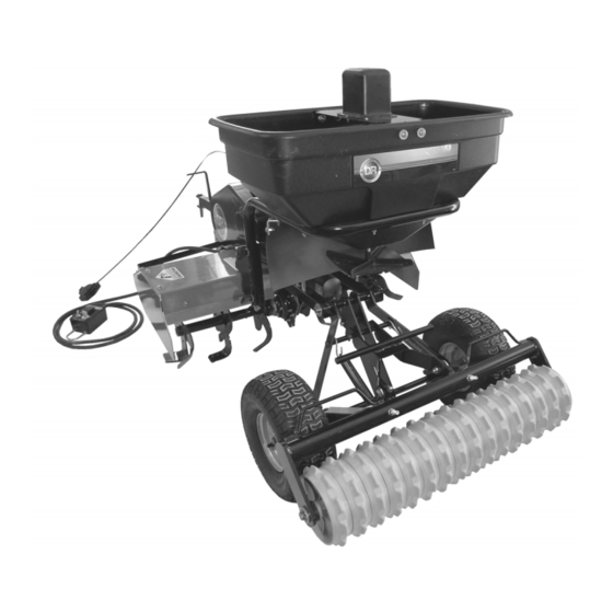
- Page 1 ® ROTO-HOG™ POWER TILLER OPTIONAL ACCESSORIES SAFETY & OPERATING INSTRUCTIONS DR Power Equipment Toll-free phone: 1-800-DR-OWNER (376-9637) Serial No. Fax: 1-802-877-1213 Order No. Website: www.DRpower.com Read and understand this manual and all instructions before using your accessory.
-
Page 2: Table Of Contents
Additional Information and Potential Changes DR Power Equipment reserves the right to discontinue, change, and improve its products at any time without notice or obligation to the purchaser. The descriptions and specifications contained in this manual were in effect at printing. Equipment described within this manual may be optional. -
Page 3: Chapter 1: General Safety Rules
Shown below are copies of all the labels that appear on the accessories. Take a moment to study them and make a note of their location on your OPTIONAL ACCESSORY for the DR ROTO-HOG POWER TILLER as you assemble and before you operate the unit. -
Page 4: Chapter 2: Setting Up Your Accessory For The Dr Roto-Hog Power Tiller
Chapter 2: Setting Up Your Accessory For The DR ROTO-HOG Power Tiller This chapter outlines a few simple steps you will need to follow to set up and use your new DR ROTO-HOG POWER TILLER OPTIONAL ACCESSORIES. If you have any questions at all, please feel free to contact our Customer Service Representatives at our toll free number 1-800-DR-OWNER (376-9637). - Page 5 Major Components Hopper Hopper/Frame Closure Assembly Plate Impeller Motor Mount Impeller Assembly Shaft Hardware Flow Package Vinyl Cover Control (see next Lever page) Assembly Screen Mounting Mounting Bracket, R.H. Bracket, L.H. Deflector Figure 2 Contact us at www.DRpower.com...
- Page 6 1/2" Wrench and Socket Instructions: 1. Remove two 5/16-18 X 2-1/4" Hex Head Bolts, Washers and Nylock Nuts Hex Head Bolts, Washers and (1/2" Wrench) from the back face of the ROTO-HOG POWER TILLER Fender Nylock Nuts (Figure 3). Figure 3 ®...
- Page 7 2. Position the left hand Mounting Bracket onto the back face of Tiller Fender Hex Head Bolt, (Figure 4), with mounting tabs facing in, and replace the hardware you Washers and removed in step 1. Install a 5/16-18 X 1” Hex Head Bolt (on top), Washer Nylock Nut and Nylon Locknut (1/2"...
- Page 8 Impeller 9. Slide the Impeller Shaft through the hole in Spreader Screen and insert the Shaft Agitator Hairpin thru the center hole in the Impeller Shaft (Figure 8). 10. Position the Motor Mount assembly with the Spreader Screen into the Agitator Hairpin Hopper and slide the Impeller Shaft through the hole in the bottom of the...
- Page 9 Wiring Instructions “ON” 1. Move the "ON-OFF" Switch on the ROTO-HOG Control Box to the “OFF” position (Figure 12). “OFF” 2. Attach the Spreader Cable Connector to the Motor Mount Assembly ROTO- Connectors (Figure 13). “ON-OFF” Control Box 3. Plug the Green Wire Connector from the Spreader Cable into the Green Wire Switch Connector from the Tiller (Figure 14).
- Page 10 SETTING UP YOUR DR CULTI-PACKER Frame and Wheel Unpacking the DR Culti-packer Transport Assembly Hook Parts Supplied: • Frame and Wheel Assembly • Transport Hook Hardware • Package Hardware Package Tools Needed: • Pliers • Utility Knife 1. Cut the plastic away from the box with a Utility Knife.
- Page 11 2. Insert the Bolts, Washers and Spacers (bolt heads facing out) and secure with the Locknuts using two 3/4" Wrenches. Installing the Culti-packer 1. Rotate the ROTO-HOG Power Tiller Wheels to their halfway position with the ROTO-HOG Control Box (Figure 19). Adjustment 2.
- Page 12 Slotted Tube/ Culti-packer 4. Slide the Slotted Tubes of the Frame Assembly onto the Lower Wheel Axle Frame Assembly of the Tiller until the Axle is seated into the slot base of both Slotted Tubes (Figure 21). 5. Insert the Clevis Pins into the holes at the ends of both Slotted Tubes from the top and secure the Clevis Pins with Hairpin Clips (Figure 22).
-
Page 13: Chapter 3: Operating Your Optional Accessory
Chapter 3: Operating Your Optional Accessory OPERATING YOUR DR POWER SPREADER Flow Control “OFF” Lever Adjustable Setting the Flow Control Lever Stop 1. Slide the Adjustable Stop to the desired setting (“OFF” is fully closed, “10” is fully open) (Figure 26). - Page 14 9. If fertilizer is accidentally deposited too heavily in an area, soak the area thoroughly with a garden hose or sprinkler to prevent burning of the lawn. Motor Removing the DR Power Spreader Mount Assembly 1. Disconnect the Wire Harness Connector from the Motor Mount Assembly Connector.
-
Page 15: Chapter 4: Maintaining The Optional Accessory
MAINTAINING THE DR POWER SPREADER When performing any maintenance on the DR Spreader Attachment when the unit is still attached to the tiller, you must first make sure the switch on the tiller control box is in the “off” position and then disconnect the wire harness of the motor mount assembly. - Page 16 MAINTAINING THE DR CULTI-PACKER Regular Maintenance Check List before each use CHECK FOR LOOSE FASTENERS 1. Before each use make a thorough visual check of the Culti-packer for any bolts and nuts which may have loosened. Retighten any loose bolts and nuts.
-
Page 17: Chapter 5: Troubleshooting Your Optional Accessory
TROUBLESHOOTING YOUR DR POWER SPREADER When performing any maintenance on the DR Spreader Attachment when the unit is still attached to the tiller, you must first make sure the switch on the tiller control box is in the “off” position and then disconnect the wire harness of the motor mount assembly. - Page 18 Notes: ® ROTO-HOG™ POWER TILLER - OPTIONAL ACCESSORIES...
- Page 19 Notes: Contact us at www.DRpower.com...
-
Page 20: Chapter 6: Parts List And Schematic Diagrams
Chapter 6: Parts List And Schematic Diagrams Parts List - DR POWER SPREADER NOTE: Part numbers listed are available through DR Power Equipment. Ref# Part# Description Ref# Part# Description 234851 Hopper 234861 Hairpin, Agitator 234811 Plug, 1/4" 233081 Nut, Hex 5/16-18 Nylock 234761 Bolt, Hex, 1/4-20"... - Page 21 Schematic - DR POWER SPREADER Contact us at www.DRpower.com...
- Page 22 Parts List - DR CULTI-PACKER NOTE: Part numbers listed are available through DR Power Equipment. Ref# Part# Description 265451 Transport Hook 264501 Bolt, Hex, 1/2" X 1-3/4" 264521 Washer, .5312" X 1.5" X .1345" 110721 Nut, Nylon Lock, 1/2" 234231 Pin, Clevis, 3/8"...
- Page 23 Schematic - DR CULTI-PACKER Contact us at www.DRpower.com...
- Page 24 M E I G S R O A D , P . O . B O X 2 5 , V E R G E N N E S , V E R M O N T 0 5 4 9 1 1-800-DR-OWNER (376-9637) • www.DR power.com...
Need help?
Do you have a question about the ROTO-HOG POWER TILLER and is the answer not in the manual?
Questions and answers