
Related Manuals for Rose electronics ServeView Pro


Summary of Contents for Rose electronics ServeView Pro
- Page 1 INSTALLATION AND OPERATIONS MANUAL 10707 Stancliff Road Phone: (281) 933-7673 Houston, Texas 77099 WWW.ROSE.COM...
- Page 2 LIMITED WARRANTY Rose Electronics warrants the ServeView Pro ™ to be in good working order for one year from the date of purchase from Rose Electronics or an authorized dealer. Should this product fail to be in good working order at any time during this one-year warranty period, Rose Electronics will, at its option, repair or replace the Unit as set forth below.
- Page 3 FCC/IC STATEMENTS, EU DECLARATION OF CONFORMITY FEDERAL COMMUNICATIONS COMMISSION AND INDUSTRY CANADA RADIO-FREQUENCY INTERFERENCE STATEMENTS This equipment generates, uses, and can radiate radio frequency energy and if not installed and used properly, that is, in strict accordance with the manufacturer’s instructions, may cause interference to radio communication.
-
Page 4: Table Of Contents
KVM station ......................3 CPU connection.......................3 ServeView Pro models....................4 ServeView Pro models (rear) ..................5 Cables ..........................6 ServeView Pro to KVM station cables ..............6 ServeView Pro to CPU cables .................6 ServeView Pro Master to Slave unit cables.............6 Keyboard command usage..................9 Organizing the system ....................10 Installation –... -
Page 5: Disclaimer
ServeView Pro is the result of Rose Electronics commitment to providing state-of-the-art switching solutions for today’s demanding workplace. The ServeView Pro has proven to be a valuable and dependable investment for users that have the need to access multiple computer systems from a single KVM station. -
Page 6: Features
Monitors VGA, SVGA, XGA, Composite, Sync-of-green Mice Standard PS/2, PS/2 wheel, Serial (2 or 3 button), USB, Sun, Apple ADB* * Requires use of Rose translator: CNV-MACPS and Rose cable. SERVEVIEW PRO INSTALLATION AND OPERATIONS MANUAL... -
Page 7: Package Contents
PC connected to the RS/232 serial port (not connected to a CPU port). If your system demands are greater than a single unit can provide, the ServeView Pro can be easily expanded to connect up to 256 computers by chaining units together with expansion cables. -
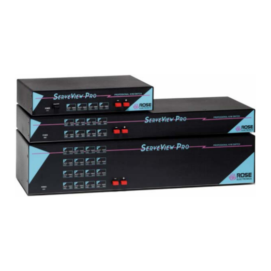
Page 8: Serveview Pro Models
- Connects to the previous CPU Switches* + Connects to the next CPU * The - and + switches are used when: upgrading the firmware resetting the unit to factory defaults running diagnostics. Table 1. Front panel SERVEVIEW PRO INSTALLATION AND OPERATIONS MANUAL... -
Page 9: Serveview Pro Models (Rear)
“B” and “C” Chassis only IEC320 Power receptacle w/switch CPU-x DB25F “M” 1-4 CPU adapter cable connectors “B” 1-8 “C” 1-16 KVM-1 DB25F KVM cable connector. RS232 RJ12 6-conductor jack Table 2. Rear panel connectors SERVEVIEW PRO INSTALLATION AND OPERATIONS MANUAL... -
Page 10: Cables
ServeView Pro to CPU cables A CPU cable is used to connect each computer to the ServeView Pro. The CPU cable connects from the DB25F CPU ports on the ServeView Pro to the keyboard, video, and mouse ports on each CPU. This cable is configured with a DB25M connector on one end and a connector for the keyboard, video, and mouse on the other end. -
Page 11: Table 3. Keyboard Commands
KEYBOARD COMMANDS Table 3 shows the keyboard commands that are available for the ServeView Pro. To issue a keyboard command, first press and release the left control [Ctrl] key, then, within 2 seconds, issue the command. <Ctrl> in the key sequence column is a press and release of the left control key. -
Page 12: Table 4. Mode Commands
Rate Rate Rate Rate Rate Rate Keys/ Value Keys/ Value Keys/ Value Keys/ Value Sec. Sec. Sec. 30.0 15.0 26.7 13.3 24.0 12.0 21.8 10.9 20.0 10.0 18.5 17.1 16.0 Table 5. Typematic value SERVEVIEW PRO INSTALLATION AND OPERATIONS MANUAL... -
Page 13: Keyboard Command Usage
The - and + keys on the keyboard, next to the backspace key vary from country to country as to their usage. These keys can still be used to connect to the next or previous computer. SERVEVIEW PRO INSTALLATION AND OPERATIONS MANUAL... -
Page 14: Organizing The System
CPU ports on the Slave unit with the most CPU ports. Installation – Single unit This section explains how to connect and initially configure the ServeView Pro. If you are cascading two or more ServeView Pro units together, please refer to the Cascade installation section. Connecting the KVM station Connect the KVM station’s keyboard, video monitor, and mouse cables to... -
Page 15: Connecting The Computers
ServeView Pro can automatically determine the keyboard and mouse types of the connected CPUs. If removing power to a computer is not feasible, the ServeView Pro should be pre-configured, if needed, before the CPU is connected. The default keyboard and mouse types set for each CPU port is a PC mode 2 keyboard and a PS/2 mouse. -
Page 16: Figure 3. Single Unit Installation
Pro. 2. Wait until the “SELECT 1” LED on the front panel lights. 3. Switch the ServeView Pro to CPU port x. (Ctrl,port #,[Enter]) (Starting with x = 1) 4. Connect the computer that has been pre-determined to be connected to the CPU port being configured using the appropriate CPU cable. -
Page 17: Installation - Cascading Units
The ports on the master unit used for expansion should not be counted. If there is a mixture of ServeView Pro models in the system, the “Maximum computers” value is the “Width” value times the number of Slave units plus the CPU ports on the master unit that are not used for expansion. -
Page 18: Connecting "Slave" Units
Issue the mode command to change the keyboard and issue the command again to change the mouse type or issue a global mode command to change all. Make sure the ServeView Pro is connected to the correct CPU port before entering the mode command. -
Page 19: Figure 4. Cascading Units
3-5 for this computer and for the remaining computers. Expansion unit #2 Expansion unit #1 CPUs 9-16 CPUs 1-8 MASTER CPU cable KVM cable CPUs 17-22 KVM-1 Station Figure 4. Cascading units SERVEVIEW PRO INSTALLATION AND OPERATIONS MANUAL... -
Page 20: Selecting A Computer From The Front Panel
OPERATION Selecting a computer To connect to a computer, you can select it from the ServeView Pro’s front panel, select it by keyboard commands, or select it through the RS232 serial port. Selecting a computer from the front panel Using the - and + buttons on the front panel will switch to the previous (-) computer port or advance (+) to the next computer. -
Page 21: Firmware Update
SERIAL PORT Serial Port (RS232) The RS232 serial port on the ServeView Pro’s rear panel is used for sending switching commands from a stand-alone computer or terminal or to load flash firmware upgrades to the unit. A serial cable and an RJ to DB9 adapter are included with the unit. - Page 22 ………………… ”Verify successful” ”Hit enter to boot” Hit enter and the ServeView Pro will re-start with the new firmware. Hit the enter key to continue. The ServeView Pro is now operational with the new firmware update. If the upgrade is not successful, you will see one of the following error...
-
Page 23: Troubleshooting
Wrong cable or keyboard and mouse cables reversed. Cable is defective; try using cable from another computer. Port on the ServeView Pro is defective; try using another port on ServeView Pro. If the problem goes away port is defective. Port on computer is defective, try plugging in keyboard or mouse directly if problem remains computer port is defective. - Page 24 Cable is defective; try using cable from another computer if problem goes away cable is defective. Port on ServeView Pro is defective; try using another port on ServeView Pro. If problem goes away port is defective. Lower resolution OK, but can’t enter high resolution mode Video driver has not been setup for this resolution.
-
Page 25: Maintenance And Repair
This Unit does not contain any internal user-serviceable parts. In the event a Unit needs repair or maintenance, you must first obtain a Return Authorization (RA) number from Rose Electronics or an authorized repair center. This Return Authorization number must appear on the outside of the shipping container. - Page 26 SAFETY Safety This ServeView Pro KVM switch has been tested for conformance to safety regulations and requirements, and has been certified for international use. Like all electronic equipment, the ServeView Pro should be used with care. To protect yourself from possible injury and to minimize the risk of damage to this Unit, read and follow these safety instructions.
-
Page 27: Safety And Emc Regulatory Statements
Servicing There are no user-serviceable parts inside these products. Only service- trained personnel must perform any servicing, maintenance, or repair. Only items mentioned in this manual may be adjusted by the user. SERVEVIEW PRO INSTALLATION AND OPERATIONS MANUAL... - Page 28 à la terre ait été réparée. Aucune pièce contenue à l’intérieur de ce produit ne peut être réparée par l’utilisateur. Tout dépannage, réglage, entretien ou réparation devra être confié exclusivement à unpersonnel qualifié. SERVEVIEW PRO INSTALLATION AND OPERATIONS MANUAL...
-
Page 29: Appendices
PC mode 2 – PS/2 CPU keyboard/mouse type PC mode 2 – PS/2 Scan time interval 5 seconds Power on scan Maximum ports Same as physical number of ports Expansion width Slave units Caps/Numlock/Scroll Numlock On SERVEVIEW PRO INSTALLATION AND OPERATIONS MANUAL... -
Page 30: Appendix B. Parts And Cables
RM-UB24 “C” (high) RM-UC19 RM-UC23 RM-UC24 The Multi-platform ServeView model support Audio or Serial devices such as graphic tablets, touchscreens and smart boards. Contact Rose sales department for more information on cable part numbers. SERVEVIEW PRO INSTALLATION AND OPERATIONS MANUAL... -
Page 31: Appendix C. General Specifications
Appendix C. General Specifications The ServeView Pro part number is Sxy-zUB Where x = platform, E = PC, SUN, Apple, Unix (Multi-platform) P = PC and Unix computers (PC) Where y = chassis size, M (mini), B (low), C (high) -
Page 32: Appendix D. Rack Mount Instructions
Appendix D. Rack mount instructions The ServeView Pro can be mounted in a rack using the Rackmount kits from Rose Electronics. The optional rack mount kit includes the following items: Two black anodized mounting brackets. Four 6-32 x 3/8” flat head mounting screws. -
Page 33: Appendix F. Keyboard Mapping
Keypad 8 Props Keypad 9 Undo Keypad 5 Front Keypad 6 Copy Keypad 2 Open Keypad 3 Paste Keypad 0 Find Keypad. Home Help Mute Page Up Volume Up Page Down Volume Down Delete Power SERVEVIEW PRO INSTALLATION AND OPERATIONS MANUAL... -
Page 34: Appendix G. Video Distance Capability
3- Very acceptable; Images clear, small reflections around colored letters 2- Acceptable: Slightly fuzzy images, readable text, acceptable usage for short periods of time, can cause eye fatigue. 1- Unusable; images smeared, text not easily readable. SERVEVIEW PRO INSTALLATION AND OPERATIONS MANUAL... - Page 36 〒103-0014 東京都中央区日本橋蛎殻町 1-16-11 TEL:03-3668-8089 FAX:03-3668-9872 URL:http://www.cybernetech.co.jp 10707 Stancliff Road Phone: (281) 933-7673 Houston, Texas 77099 WWW.ROSE.COM...
Need help?
Do you have a question about the ServeView Pro and is the answer not in the manual?
Questions and answers