Napoleon HD81NT Installation And Operating Instructions Manual
Hide thumbs
Also See for HD81NT:
- Installation and operating instructions manual (124 pages) ,
- Installation and operating instructions manual (116 pages) ,
- Installation and operating instructions manual (52 pages)
Table of Contents
Advertisement
Quick Links
CERTIFIED UNDER CANADIAN AND AMERICAN NATIONAL STANDARDS: CSA 2.33, ANSI Z21.88 FOR VENTED GAS HEATERS.
HD81NT
NATURAL GAS
HD81PT
PROPANE
CERTIFIED FOR CANADA AND UNITED STATES USING ANSI/CSA METHODS.
SAFETY INFORMATION
WARNING
!
If the information in these instructions are
not followed exactly, a fire or explosion
may result causing property damage,
personal injury or loss of life.
- Do not store or use gasoline or other
flammable vapors and liquids in the vicinity
of this or any other appliance.
- WHAT TO DO IF YOU SMELL GAS:
Do not try to light any appliance.
Do not touch any electrical switch; do
not use any phone in your building.
Immediately call your gas supplier from
a neighbour's phone. Follow the gas
supplier's instructions.
If you cannot reach your gas supplier,
call the fire department.
-
Installation
and
performed by a qualified installer, service
agency or the supplier.
Phone (705)721-1212 • Fax (705)722-6031 • www.napoleonfireplaces.com • ask@napoleon.on.ca
$10.00
INSTALLER: LEAVE THIS MANUAL WITH THE APPLIANCE.
CONSUMER: RETAIN THIS MANUAL FOR FUTURE REFERENCE.
INSTALLATION AND
OPERATING INSTRUCTIONS
service
must
Wolf Steel Ltd., 24 Napoleon Rd., Barrie, ON, L4M 4Y8 Canada /
103 Miller Drive, Crittenden, Kentucky, USA, 41030
be
Serial No.
APPLY SERIAL NUMBER LABEL FROM CARTON
MODEL NO.
W415-0687 / 12.02.08
1
W415-0687 / 12.02.08
Advertisement
Table of Contents

Related Manuals for Napoleon HD81NT


Summary of Contents for Napoleon HD81NT
-
Page 1: Safety Information
Serial No. agency or the supplier. MODEL NO. Wolf Steel Ltd., 24 Napoleon Rd., Barrie, ON, L4M 4Y8 Canada / 103 Miller Drive, Crittenden, Kentucky, USA, 41030 Phone (705)721-1212 • Fax (705)722-6031 • www.napoleonfireplaces.com • ask@napoleon.on.ca $10.00 W415-0687 / 12.02.08... -
Page 2: Table Of Contents
TABLE OF CONTENTS INTRODUcTION WARRANTy DIMENSIONS INSTALLATION OVERVIEW GENERAL INSTRUCTIONS GENERAL INFORMATION CARE OF GLASS CARE OF pLATED pARTS vENTING VENTING LENGTHS AND COMpONENTS MINIMUM AIR TERMINAL LOCATION CLEARANCES VENT AppLICATION FLOW CHART DEFINITIONS ELbOW VENT LENGTH VALUES HORIZONTAL TERMINATION VERTICAL TERMINATION INSTALLATION WALL AND CEILING pROTECTION... -
Page 3: Introduction
1.0 INTrOduCTION WARNING • Do not operate heater before reading and understanding operating instructions. Failure to operate heater according to operating instructions could cause fire or injury. • Risk of fire or asphyxiation do not operate heater with fixed glass removed. •... -
Page 4: Warranty
NAPOLEON® warrants its products against manufacturing defects to the original purchaser only. Registering your warranty is not necessary. Simply provide your proof of purchase along with the model and serial number to make a warranty claim. NAPOLEON® reserves the right to have its representative inspect any product or part thereof prior to honouring any warranty claim. -
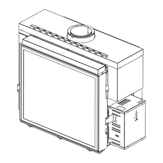
Page 5: Dimensions
dImENSIONS 24 5/8” fIGURE 1.2a-c 12 5/16” 52” 39” 40 3/8” 33 1/2” 14 3/4” 10 5/8” 1 1/2” 25 1/2” 26 3/8” 39” ELECTRICAL INLET 1 3/8” CONNECTION INSTALLATION OvErvIEw fIGURE 1.3 See the section “FRAMING - See the section MINIMUM MANTEL “VENTING - VENTING CLEARANCES”... -
Page 6: General Instructions
gENErAL INSTruCTIONS WARNING Always light the pilot whether for the first time or if the gas supply has ran out, with the glass door opened or removed. Provide adequate accessibility clearance for servicing and operating the fireplace. Provide adequate ventilation. Never obstruct the front opening of the fireplace. -
Page 7: General Information
gENErAL INFOrmATION fOR yOUR SATISfAcTION, THIS fIREPLAcE HAS bEEN TEST-fIRED TO ASSURE ITS OPERATION AND qUALITy! Maximum input is 60,000 BTU/hr for natural gas and 50,000 BTU/hr for propane. When the fireplace is installed at elevations above 4,500ft, and in the absence of specific recommendations from the local authority having jurisdiction, the certified high altitude input rating shall be reduced at the rate of 4% for each additional 1,000ft. -
Page 8: Venting
2.0 vENTINg WARNING Risk of fire, maintain specified air space clearances to vent pipe and appliance. This fireplaces uses 8" exhaust / 10" air intake vent pipe system. Refer to the section applicable to your installation. For safe and proper operation of the fireplace follow the venting instruction exactly. Deviation from the minimum vertical vent length can create difficulty in burner start-up and/or carboning. - Page 9 16” MINIMUM 40 FEET MAxIMUM 3 FEET MINIMUM 36” MAxIMUM 24” MINIMUM 64 1/4” pLUS RISE 40 1/4” 40 1/4” fIGURE 2.1b fIGURE 2.1a Tp - VENT LENGTHS W415-0687 / 12.02.08...
-
Page 10: Minimum Air Terminal Location Clearances
mINImum AIr TErmINAL LOCATION CLEArANCES fIGURE 2.2 Tp - MINIMUM AIR TERMINAL LOCATIONS-HD81 W415-0687 / 12.02.08... -
Page 11: Vent Application Flow Chart
vENT AppLICATION FLOw ChArT Horizontal Termination Vertical Termination Vertical rise Vertical rise is equal Vertical rise is less Vertical rise is equal is less than to or greater than the than horizontal run to or greater than horizontal run horizontal run the horizontal run Horizontal run + Horizontal run +... -
Page 12: Horizontal Termination
hOrIzONTAL TErmINATION ) < (V Simple venting configuration (only one 90° elbow) See graph to determine the required vertical rise V for the required horizontal run H REQUIRED VERTICAL RISE IN FEET V fIGURE 2.6a 12.5 17.5 HORIZONTAL VENT RUN PLUS OFFSET IN FEET H The shaded area within the lines represents acceptable values for H and V... - Page 13 ) > (V Simple venting configuration (only one 90° elbow) See graph to determine the required vertical rise V for the required horizontal run H 147” REQUIRED fIGURE 2.6c VERTICAL RISE IN INCHES V 57” 19 1/2” 2’ 12.5’ HORIZONTAL VENT RUN PLUS OFFSET IN FEET H The shaded area within the lines represents acceptable values for H and V...
-
Page 14: Vertical Termination
vErTICAL TErmINATION ) < (V Simple venting configurations. See graph to determine the required vertical rise V for the required horizontal run H fIGURE 2.7a REQUIRED VERTICAL RISE IN FEET V HORIZONTAL VENT RUN PLUS OFFSET IN FEET H The shaded area within the lines represents acceptable values for H and V For vent configurations requiring more than zero 90°... - Page 15 ) > (V Simple venting configurations. See graph to determine the required vertical rise V for the required horizontal run H REQUIRED VERTICAL RISE IN FEET V HORIZONTAL VENT RUN PLUS OFFSET IN FEET H fIGURE 2.7c The shaded area within the lines represents acceptable values for H and V For vent configurations requiring more than two 90°...
-
Page 16: Installation
3.0 INSTALLATION WARNING Follow the venting instructions exactly. All inner exhaust and outer intake vent pipe joints may be sealed using either red RTV high temp silicone sealant W573-0002 (not supplied) or black high temp mill pac W573-0007 (not supplied) with the exception of the fireplace exhaust flue collar which must be sealed using mill pac. -
Page 17: Vertical Installation
vErTICAL INSTALLATION This application occurs when venting through a roof. Installation kits for various roof pitches are available from your GD36 FIRESTOP SLEEVE ASSEMBLY Authorized dealer / distributor. See accessories to order specific kits required. A. Determine the air terminal location, cut and frame 14 1/2” square opening in fIGURE 3.3a the ceiling and the roof to provide the minimum 2“... -
Page 18: Horizontal Air Terminal Installation
hOrIzONTAL AIr TErmINAL INSTALLATION fIGURE 3.5a NOTE: Direct vent terminals shall not be recessed into a wall or siding. #10x2" SCREWS A. Stretch the 8" flexible vent pipe to the required length taking into account the additional length needed for the finished wall surface. Slip the vent CAULKING pipe a minimum of 2"... -
Page 19: Vertical Air Terminal Installation
vErTICAL AIr TErmINAL INSTALLATION WARNING Maintain a minimum 2” space between the air inlet base and the storm collar. fIGURE 3.6a A. Fasten the roof support to the roof using the screws provided. The roof support is optional. In this case the venting is to be adequately supported using either an alternate method suitable to the authority having jurisdiction or the optional roof support. -
Page 20: Mobile Home Installation
mOBILE hOmE INSTALLATION This appliance is certified to be installed as an OEM (Original Equipment Manufacturer) installation in a manufactured home or mobile home and must be installed in accordance with the manufacturer’s instructions and the Manufactured Home Construction and Safety Standard, Title 24 CFR, Part 3280, in the United States or the Mobile Home Standard, CAN/CSA Z240 MH Series, in Canada. -
Page 21: Gas Installation
gAS INSTALLATION WARNING Risk of fire, explosion or asphyxiation. Ensure there are no ignition sources such as sparks or open flames. Support gas control when attaching pipe to prevent bending gas line. Always light the pilot whether for the first time or if the gas supply has run out with the glass door opened or removed. -
Page 22: Framing
4.0 FrAmINg WARNING In order to avoid the possibility of exposed insulation or vapour barrier coming in contact with the fireplace body, it is recommended that the walls of the fireplace enclosure be “finished” (ie: drywall / sheetrock), as you would finish any other outside wall of a home. This will ensure that clearance to combustibles is maintained within the cavity. - Page 23 WARNING Do not build into this area - it must be left clear to provide adequate clearance for the vent in this 14” wide area centered along the front of the fireplace. No combustibles are allowed. Fireplace should be in its final location before framing. fIGURE 4.0 84”* MINIMUM...
-
Page 24: Hearth Extension
hEArTh ExTENSION While a hearth extension is not required for this fireplace, one is recommended for aesthetic reasons. The installation of a 1” hearth extension will conceal the 1” gap under the fireplace. The hearth extension must not be any more than 1”... -
Page 25: Inside Frame Assembly
4.2.1 INSIdE FrAmE ASSEmBLy WARNING Edges are sharp, always wear gloves when working with sheet metal. WARNING A. Lay out inside steel studs (3) and center steel studs (5) fIGURE 4.2.1 on a large flat surface. b. Using the screws provided (8), attach the top steel header (6) to the inside steel studs (3) and to the center steel studs (5) on both edges. -
Page 26: Attach The Assembled Frame To The Unit
4.2.3 ATTACh ThE ASSEmBLEd FrAmE TO ThE uNIT A. Align the frame assembly to the framing Top Steel brackets and secure with screws Stud provided. The frame assembly fIGURE 4.2.3 should be flush with the front of the stud shield. Stud Shield b. -
Page 27: Minimum Clearance To Combustible Enclosures
mINImum CLEArANCE TO COmBuSTIBLE ENCLOSurES WARNING Risk of fire! The front of the fireplace must be finished with any non-combustible materials such as brick, marble, granite, etc., provided that these materials do not cover the fireplace opening. The steel stud framing kits with cement board provided, must be installed. ImPORTANT: The HD81 requires a minimum inside enclosure height of 84”, measured from the bottom of the fireplace. -
Page 28: Minimum Mantel Clearances
COMBUSTIBLE MATERIAL STEEL STUD fIGURE 4.3b FRAMING NON-COMBUSTIBLE 15 3/4” MATERIAL 7 5/8” 39” 54 1/4” 49 1/4” 33 1/2” 7 5/8” mINImum mANTEL CLEArANCES WARNING Risk of fire, maintain all specified air space clearances to combustibles. Failure to comply with these instructions may cause a fire or cause the appliance to overheat. -
Page 29: Finishing
5.0 FINIShINg dOOr rEmOvAL / INSTALLATION WARNING Glass may be hot, DO NOT touch glass until cooled. The door latches are part of a safety system and must be properly engaged. Do not operate the fireplace with latches disengaged. Facing and/or finishing materials must not interfere with air flow through air openings, louvres openings, operation of louvres or doors or access for service. -
Page 30: Electrical Connection
6.0 ELECTrICAL CONNECTION WARNING Do not use this heater if any part has been under water. Call a qualified service technician IMMEDI- ATELY to have the fireplace inspected for damage to the electrical circuit. Risk of electrical shock or explosion. Do not wire 110V to the valve or to the appliance wall switch. Incorrect wiring will damage controls. -
Page 31: Schematic
SChEmATIC fIGURE 6.3 ACS/IPI Switch Spark Electrode Flame Night Lights Sensor Pilot 120V OUT AUX OUT POWER Control Module Valve Pilot Electronic Modulation Ground Wire Receiver IPI Board Wire Wire Harness Wire Harness Assembly Harness Plug W415-0687 / 12.02.08... -
Page 32: Operation
7.0 OpErATION gENErAL TrANSmITTEr LAyOuT TRANSMISSION fIGURE 7.1 THERMOSTAT CHILD SAFETY OFF/ON/SMART LOCK OUT ROOM LOW BATTERY TEMPERATURE ALARM TEMPERATURE SET POINT/ LEVEL/ STATUS FLAME AUX. OUTPUT SPLIT VALVE FIrEpLACE OpErATION ● Install 4 AA batteries into the receiver battery bay as indicated on the battery cover (+/-). (Only required as back up to household electricity). -
Page 33: Temperature Display
TEmpErATurE dISpLAy ● With the system in the “OFF” position, press the °F °C Thermostat Key and the Mode Key at the same time to change from degrees F to C. ● Look at the LCD screen on the Transmitter to verify that a C or F is visible to the right of the Room Temperature display. -
Page 34: Fan Speed
FAN SpEEd If the appliance is equipped with a hot air circulating fan, °F °F the speed of the fan can be controlled by the remote system. The fan speed can be adjusted through six (6) speeds. ● Use the Mode key to guide you to the fan control icon. -
Page 35: Low Battery / Manual Bypass
7.12 LOw BATTEry / mANuAL BypASS The life span of the remote batteries depends on various factors: quality of the °F batteries, the number of ignitions, the number of charges to the room thermostat set point, etc. When the transmitter batteries are low, a Battery Icon will appear on the LCD display before all battery power is lost. -
Page 36: Rating Plate/Lighting Instruction Location
THE APPLIANCE MUST BE VENTED USING THE APPROPRIATE L'APPAREIL DOIT ÉVACUER SES GAZ EN UTILISANT L'ENSEMBLE FRAMING MATERIALS. FOR FINISHING MATERIALS ARRIÉRE NAPOLEON VENT KITS. SEE OWNERS INSTALLATION MANUAL D'ÉVACUATION PROPRE A NAPOLEON. RÉFÉRER AU MANUEL SEE OWNERS MANUAL DESSUS, COTÉS & ARRIÈRE: SELON LES ESPACEURS FOR VENTING SPECIFICS. -
Page 37: Operating Instructions
6. Check to see that the main burner ignites completely on all openings when turned on. A 5 to 10 second total light-up W415-0687 / 12.02.08 period is satisfactory. If ignition takes longer, consult your Napoleon dealer / distributor. 7. Check that the gasketing on the sides, top and bottom of the door is not broken or missing. Replace if necessary. -
Page 38: Maintenance
6. Check to see that the main burner ignites completely on all openings when turned on. A 5 to 10 second total light-up period is satisfactory. If ignition takes longer, consult your Napoleon dealer / distributor. 7. Check that the gasketing on the sides, top and bottom of the door is not broken or missing. Replace if necessary. -
Page 39: Remote Receiver Removal
11.2 rEmOTE rECEIvEr rEmOvAL A. Remove inner access panel, see “INNER ACCESS PANEL” section. b. Remove the 2 screws holding the receiver in place. Once CONTROL MODULE removed pull the wire harness plug out from the rear of the receiver. c. -
Page 40: Valve Removal
11.4 vALvE rEmOvAL fIGURE 11.4 The valve on the HD81 is piped with three flex connectors (one inlet, two outlets). It can be removed and pulled forward for service. A. Remove inner access panel, see “INNER ACCESS PANEL” section. b. Remove the wing nut and pivot the valve out from WING the slot at the bottom of the valve. -
Page 41: Adjustment
12.0 AdjuSTmENT 12.1 pILOT BurNEr AdjuSTmENT Adjust the pilot screw to provide properly sized flame. Turn in a clockwise direction to reduce the gas flow. Check Pressure Readings: Inlet pressure can be checked by turning screw (A) counter-clockwise 2 or 3 turns and then placing pressure gauge tubing over the test point. -
Page 42: Replacements
W725-0057 pROpANE GAS MODULATING ELEC. VALVE W725-0058 SpLIT FLOW VALVE W010-1797 FIRESTOp SpACER ASSEMbLy W010-1871 MAIN DOOR ASSEMbLy W010-1958 GLASS C/W GASkET W385-0334 NApOLEON® LOGO W720-0062 pILOT TUbE W190-0029 IpI IGNITION bOARD W660-0069 CONTROL MODULE W660-0075 S-RECEIVER W707-0006 TRANSFORMER W660-0071... - Page 43 TErmINAL kIT REf NO. HD81 DEScRIPTION W010-0067 WALL SUppORT ASSEMbLy rOOF TErmINAL kITS REf NO. HD81 DEScRIPTION GD622R WALL TERMINAL kIT GD610 1/12 TO 7/12 pITCH GD611 8/12 TO 12/12 pITCH GD612 FLAT ROOF W490-0075 8/10 AIR TERMINAL CONNECTOR W670-0008 8/10 TERMINAL W170-0016 STORM COLLAR...
-
Page 44: Trouble Shooting
14.0 TrOuBLE ShOOTINg EFORE ATTEMPTING TO TROUBLESHOOT PURGE YOUR UNIT AND INITIALLY LIGHT THE PILOT AND THE MAIN BURNER WITH THE GLASS DOOR OPEN SYMPTOM PROBLEM TEST SOLUTION - Remove blockage. In really cold conditions, ice buildup Main burner Blockage in vent. may occur on the terminal and should be removed as flame is a blue, required. - Page 45 SYMPTOM PROBLEM TEST SOLUTION - Verify the wire for the sensor and the wire for the ignitor Pilot will not light. Wiring. are connected to the correct terminals (not reverse) on Makes noise with the module and pilot assembly. no spark at pilot burner.
- Page 46 SYMPTOM PROBLEM TEST SOLUTION - Verify all connections. Verify the connections from the Continues to Short or loose connection pilot assembly are tight; also verify these connections are spark and pilot in sensor rod. not grounding out to any metal. lights, but main burner will not - Verify the flame is engulfing the sensor rod.
-
Page 47: Fireplace Service History
15.0 FIrEpLACE SErvICE hISTOry Tp - SERVICE HISTORy W415-0687 / 12.02.08... -
Page 48: Notes
16.0 NOTES Tp - NOTES W415-0687 / 12.02.08...
Need help?
Do you have a question about the HD81NT and is the answer not in the manual?
Questions and answers