Table of Contents
Advertisement
Quick Links
Download this manual
See also:
Administrator's Manual
Advertisement
Chapters
Table of Contents

Related Manuals for SMART SBID8055i-G5-SMP


Summary of Contents for SMART SBID8055i-G5-SMP
- Page 1 Help us make this document better smarttech.com/docfeedback/170814 SMART Board® 8000i-G5-SMP series interactive flat panels ADMINISTRATOR’S GUIDE FOR MODEL SBID8055i-G5-SMP...
- Page 2 © 2015 SMART Technologies ULC. All rights reserved. No part of this publication may be reproduced, transmitted, transcribed, stored in a retrieval system or translated into any language in any form by any means without the prior written consent of SMART Technologies ULC. Information in this manual is subject to change without notice and does not represent a commitment on the part of SMART.
-
Page 3: Important Information
Do not open or disassemble the SMART product. You risk electrical shock from the high voltage inside the casing. Opening the casing also voids your warranty. Do not stand (or allow children to stand) on a chair to touch the surface of your SMART product. Rather, mount the product at the appropriate height. - Page 4 Avoid setting up and using the SMART product in an area with excessive levels of dust, humidity and smoke. Make sure an electrical socket is near your SMART product and remains easily accessible during use.
- Page 5 IMPORTANT INFORMATION You must connect the USB cable that came with your interactive flat panel to a computer that has a USB compliant interface and that bears the USB logo. In addition, the USB source computer must be compliant with CSA/UL/EN 60950 and bear the CE mark and CSA and/or UL Mark(s) for CSA/UL 60950.
-
Page 7: Table Of Contents
Contents Important information Chapter 1: Welcome About this guide About your interactive flat panel About SMART software Resources for administrators Resources for others Chapter 2: Mounting your interactive flat panel Before mounting your interactive flat panel Choosing a location Choosing a height... - Page 8 CONTENTS Using the SMART Connection Wizard Using SMART Board Diagnostics Appendix A: Using the on-screen display menu Changing settings in the on-screen display menu On-screen display menu options Appendix B: Remotely managing your interactive flat panel Connecting and configuring a room control system Power modes Room control system programming commands and responses...
-
Page 9: About This Guide
Resources for decision makers Resources for installers Resources for users This chapter introduces you to your SMART Board® interactive flat panel and this guide. About this guide This guide explains how to set up and maintain your interactive flat panel. It includes the following... -
Page 10: Chapter 1 Welcome
Other documentation and resources are available for individuals who use interactive flat panels. About your interactive flat panel Your SMART Board® interactive flat panel features SMART’s proprietary DViT® (Digital Vision Touch) technology on an LCD screen with e-LED backlight. Specifications Refer to your interactive flat panel’s specifications for detailed technical information, including... -
Page 11: Components
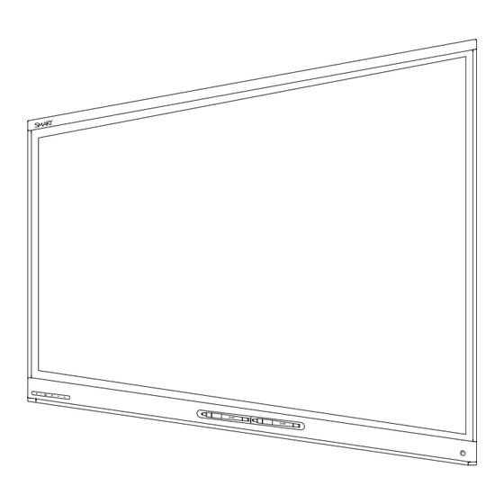
CHAPTER 1 WELCOME Components Your interactive flat panel consists of the following components: Name More information Pictured Screen Page 4 Cameras and reflective tape channel Page 4 Front control panel Page 5 Pen with eraser (×2) Page 6 Presence detection sensor Page 6 Not pictured Speakers Page 6 Connector panel... -
Page 12: Screen
CHAPTER 1 WELCOME Screen The following are the screen specifications for the SMART Board 8055i-G5-SMP interactive flat panel: Specification Value Diagonal 54 1/2" (138.4 cm) Width 47 5/8" (121 cm) Height 26 3/4" (68 cm) Aspect ratio 16:9 For information on cleaning the screen, see Cleaning the screen on page 24. -
Page 13: Front Control Panel
No USB connection from the Verify your connections (see page 15). connected computer Slowly flashing SMART Board service not Ensure that SMART Product Drivers is white running on the connected installed and that the SMART Board computer service is running. Solid white Normal operation [N/A] smarttech.com/kb/170814... -
Page 14: Pens With Erasers
CHAPTER 1 WELCOME Pens with erasers Your interactive flat panel comes with two pens with erasers attached. The bottom bezel of the interactive flat panel includes magnetic holders for the pens. Removing a pen from the holders activates it and enables you to either draw or erase digital ink. CAUTION When returning the pen to the magnetic holder, ensure that it is centered in its holder to prevent it from falling and potentially being damaged. -
Page 15: About Smart Software
CAUTION The accessory slot is for use with SMART accessories only. The slot’s maximum available power is 60 W. The slot is not a limited power source. To reduce the risk of fire, ensure accessories connecting to the slot satisfy the fire enclosure requirements of IEC 60950-1. -
Page 16: Resources For Administrators
PDF version from smarttech.com/kb/170810. Resources for users Users can refer to the SMART Meeting Pro software Help for information on using the software with the interactive flat panel. To open the Help, users can select Help > Contents in Whiteboard mode. -
Page 17: Chapter 2: Mounting Your Interactive Flat Panel
Save all product packaging so that it’s available if you need to transport the interactive flat panel. If the original packaging isn’t available, you can purchase new product packaging from your authorized SMART reseller (smarttech.com/where). Refer to local building codes to ensure the wall can support the weight of the interactive flat panel (106 lb. (48.2 kg)) and mounting equipment. -
Page 18: Choosing A Location
Do not over-tighten the screws. NOTE SMART recommends M8 × 30 mm mounting screws for standard installations where the total wall mount bracket and washer thickness is less than 7 mm. Because the receptacles might not be easily accessible after the installers mount the... -
Page 19: Choosing A Height
CHAPTER 2 MOUNTING YOUR INTERACTIVE FLAT PANEL Choosing a height Consider the general height of the user community when you choose the height for the interactive flat panel. smarttech.com/kb/170814... -
Page 21: Chapter 3: Connecting Power And Devices
Chapter 3 Connecting power and devices Connector panel Connecting power Connecting the room computer Connecting cables for a guest laptop Connecting external speakers Using the USB receptacle This chapter includes information on connecting your interactive flat panel to power, computers and other devices. smarttech.com/kb/170814... -
Page 22: Connector Panel
Guest laptop (data) See page 16. HDMI Guest laptop (video) See page 16. Stereo 3.5 mm [N/A] This connector is not available for SMART Board 8000i-G5-SMP series interactive flat panels. HDMI Room computer (video) See page 15. USB Type-B Room computer (data) See page 15. -
Page 23: Connecting Power
OPS/HDMI2. NOTE If the I/O extension module is installed, three values appear when you press the Input Select button: HDMI, OPS/HDMI2 and DisplayPort. DisplayPort is not an available input for SMART Board 8055i-G5-SMP interactive flat panels. smarttech.com/kb/170814... -
Page 24: Connecting Cables For A Guest Laptop
Connect USB and HDMI cables to the appropriate connectors on the interactive flat panel. You can then run the cables across floors or behind walls to the conference table. WARNING Ensure that any cables extending across the floor to your SMART product are properly bundled and marked to avoid a trip hazard. Connecting external... -
Page 25: Chapter 4: Setting Up Your Interactive Flat Panel And The Room Computer
Turning on your interactive flat panel and the room computer for the first time Installing SMART software Running the connection wizard This chapter explains how to set up your interactive flat panel and the room computer after mounting your interactive flat panel and connecting power and devices. -
Page 26: Installing Smart Software
2. Press Connection Wizard. The SMART Connection Wizard appears. 3. Select the interactive flat panel from the list of connected SMART interactive products, and then press Next. 4. Select Product is being set up for the first time, and then press Next. -
Page 27: Chapter 5: Maintaining Your Interactive Flat Panel
Chapter 5 Maintaining your interactive flat panel Resetting your interactive flat panel Maintaining your interactive flat panel software and firmware Opening SMART Settings Updating firmware Updating software Orienting your interactive flat panel Calibrating your interactive flat panel Maintaining your interactive flat panel hardware Checking the interactive flat panel installation... -
Page 28: Maintaining Your Interactive Flat Panel Software And Firmware
SMART Settings appears. Updating firmware Your interactive flat panel uses firmware on its processor. After you update SMART software, a new firmware executable file could save on your computer. When you connect a computer with this file to your interactive flat panel, your interactive flat panel detects this executable file, and then prompts you to run the file to update the firmware. -
Page 29: Updating Software
3. Follow the on-screen instructions using your computer’s mouse and keyboard. Don’t touch the interactive flat panel’s screen. 4. Select the check box for the SMART product you want to update, and then click Next. A progress bar appears. 5. When the installation is complete, calibrate your interactive flat panel (see Calibrating your interactive flat panel on the next page). -
Page 30: Orienting Your Interactive Flat Panel
Digital cameras in the corners of the interactive flat panel track the position of the pens, eraser and your finger on the interactive surface, and then send the information to the SMART software, which interprets this information as mouse clicks, digital ink or ink removal in the appropriate location. -
Page 31: Maintaining Your Interactive Flat Panel Hardware
CHAPTER 5 MAINTAINING YOUR INTERACTIVE FLAT PANEL 3. If you have more than one SMART product connected, select the interactive flat panel. 4. Select Advanced Settings from the drop-down list. 5. Press Calibrate. The calibration screen appears. This can take a few moments. -
Page 32: Cleaning The Screen
CHAPTER 5 MAINTAINING YOUR INTERACTIVE FLAT PANEL Cleaning the screen Follow these instructions to clean the interactive flat panel screen without damaging its anti-glare coating or other product components. CAUTION Do not use permanent or dry-erase markers on the screen. If dry-erase markers are used on the screen, remove the ink as soon as possible with a lint-free, non-abrasive cloth. -
Page 33: Cleaning The Presence Detection Sensor
CHAPTER 5 MAINTAINING YOUR INTERACTIVE FLAT PANEL To clean the camera windows and reflective tape 1. With a clean lint-free cloth, gently wipe the camera windows in the top corners and the reflective tape along the top of your interactive flat panel screen using the cloth. 2. -
Page 34: Removing And Transporting Your Interactive Flat Panel
4. Leave the interactive flat panel turned off for 48 hours. Maintaining pens To prevent damage to your interactive flat panels’ anti-glare coating, replace a pen if its nib becomes worn. You can purchase replacement pens from the Store for SMART Parts (see smarttech.com/Support/PartsStore). Removing and transporting your interactive flat panel... -
Page 35: Transporting Your Interactive Flat Panel
This packaging was designed with optimal shock and vibration protection. If your original packaging isn’t available, you can purchase the same packaging directly from your authorized SMART reseller (smarttech.com/where). CAUTION Transport your interactive flat panel only in original or replaced packaging. Transporting your interactive flat panel without correct packaging voids your warranty and could lead to product damage. -
Page 37: Chapter 6: Troubleshooting
SMART Support (smarttech.com/support/entsupport). Locating the interactive flat panel serial number When you contact SMART Support, you might be asked to provide the interactive flat panel serial number. The serial number is located in two places: The on-screen display menu (see Serial Number on page 39) -
Page 38: Resolving Presence Detection Issues
CHAPTER 6 TROUBLESHOOTING Resolving presence detection issues Use the following table to resolve presence detection issues: Symptom Cause Solution Your interactive flat panel isn’t Presence detection isn’t enabled. Enable presence detection (see page 38). turning on. There isn’t enough difference Reduce the room temperature. between the room temperature and human body temperature. -
Page 39: Resolving Touch Issues
Symptom Cause Solution When you touch the screen, the You aren’t touching the screen at a For more information, see Touching and drawing on your SMART Board interactive pointer appears in the wrong right angle. location. whiteboard is inaccurate (knowledgebase.force.com/ ?q=000013976). - Page 40 If this improves the image quality, consider replacing the video card in the original computer. SMART Product Drivers isn’t Download and install The SMART Board icon doesn’t installed. SMART Product Drivers from appear. smarttech.com/downloads. SMART Product Drivers isn’t Start SMART Product Drivers following the running. steps in the Help. smarttech.com/kb/170814...
-
Page 41: Using The Smart Connection Wizard
Using the SMART Connection Wizard You can resolve a variety of issues using the SMART Connection Wizard found in SMART Settings. To use the SMART Connection Wizard 1. Access the SMART Connection Wizard by opening SMART Settings (see Opening SMART Settings on page 20). -
Page 42: Using Smart Board Diagnostics
Using SMART Board Diagnostics If you touch the interactive flat panel’s surface and nothing happens, or if there is no digital ink or the ink appears in some locations and not in others, use SMART Board Diagnostics to help identify and resolve these issues. -
Page 43: Appendix A: Using The On-Screen Display Menu
Appendix A Using the on-screen display menu Changing settings in the on-screen display menu On-screen display menu options You can access the on-screen display menu using the menu control panel located on the side of the interactive flat panel. Name MENU [Up] [Down]... -
Page 44: On-Screen Display Menu Options
APPENDIX A USING THE ON-SCREEN DISPLAY MENU 4. Press the left and right arrows to change the menu option’s setting. Press the right arrow to open the menu option’s submenu. (Repeat steps 3 and 4 to change settings in the submenu.) 5. - Page 45 APPENDIX A USING THE ON-SCREEN DISPLAY MENU Option Values Function Notes (if any) Movie Mode Sets the brightness, contrast, black level, color and sharpness for movie watching Middle High [N/A] Resets all options in the Picture Picture Reset menu to their default values Sound Sound Mode Treble...
- Page 46 Lync® Room Reset [N/A] Resets options in all menus to their default values (for a SMART Room System™ for Microsoft® Lync) Setup Reset [N/A] Restores the setup settings to their default value...
- Page 47 APPENDIX A USING THE ON-SCREEN DISPLAY MENU Option Values Function Notes (if any) Serial Number [N/A] Displays the interactive flat panel’s This option only provides serial number information. You’re unable to modify it. Scalar firmware version [N/A] Displays the interactive flat panel’s This option only provides scalar firmware version information.
-
Page 49: Appendix B: Remotely Managing Your Interactive Flat Panel
Appendix B Remotely managing your interactive flat panel Connecting and configuring a room control system Connecting a computer to an interactive flat panel Configuring the computer’s serial interface settings Power modes Room control system programming commands and responses Command inventory Viewing a list of available commands Identifying current values Assigning a specific value Increasing a value for a setting... -
Page 50: Connecting A Computer To An Interactive Flat Panel
APPENDIX B REMOTELY MANAGING YOUR INTERACTIVE FLAT PANEL Connecting a computer to an interactive flat panel To connect a computer to the interactive flat panel Connect an RS-232 cable from the serial output on the computer to the room control input on the connector panel. -
Page 51: Power Modes
APPENDIX B REMOTELY MANAGING YOUR INTERACTIVE FLAT PANEL Power modes An interactive flat panel has three distinct power modes: Power Save Standby All commands are available when the interactive flat panel is on. Some commands are available when the interactive flat panel is in Standby mode. Room control system programming commands and responses To access interactive flat panel information or to adjust interactive flat panel settings using the... -
Page 52: Command Inventory
APPENDIX B REMOTELY MANAGING YOUR INTERACTIVE FLAT PANEL Command inventory The interactive flat panel responds to the commands in the tables on the following pages. Viewing a list of available commands You can view a list of available commands by typing ? at the command prompt. Identifying current values You can identify the current value for each setting. -
Page 53: Commands
APPENDIX B REMOTELY MANAGING YOUR INTERACTIVE FLAT PANEL Identifying the value for a video control setting Use the get command to identify values for a video control setting. In the example below, the user wants to identify the contrast for the HDMI1 video input. >get contrast hdmi1 contrast hdmi1=65 Assigning a value for a video control setting... -
Page 54: Source
APPENDIX B REMOTELY MANAGING YOUR INTERACTIVE FLAT PANEL Source Use the following commands to identify source settings. Command Response Possible values Standby mode input= [Value] get input hdmi1 ops/hdmi2 displayport get videoinputs videoinputs= [Value] hdmi1,ops/hdmi2,displayport Use the following commands to assign source settings. Command Possible values Response... -
Page 55: Audio Control
APPENDIX B REMOTELY MANAGING YOUR INTERACTIVE FLAT PANEL Use the following commands to assign video control settings. Command Possible values Response Standby mode set displaymode [Value] =standard displaymode= [Value] =user =dynamic set contrast [Value] + [Incremental value] contrast= [Value] - [Incremental value] =0–100 set brightness [Value] + [Incremental value]... - Page 56 APPENDIX B REMOTELY MANAGING YOUR INTERACTIVE FLAT PANEL Command Response Possible values Standby mode get audioinput audioinput= [Value] usbaudio HDMI DisplayPort OPSdigital get treble treble= [Value] 0–100 get bass bass= [Value] 0–100 audioeq120= [Value] get audioeq120 0–100 get audioeq500 audioeq500= [Value] 0–100 get audioeq1200 audioeq1200= [Value] 0–100...
-
Page 57: System Information
APPENDIX B REMOTELY MANAGING YOUR INTERACTIVE FLAT PANEL System information Use the following commands to identify system information settings. Command Response Possible values Standby mode autopoweroff= [Value] get autopoweroff 15–240 get fwverscr fwverscr= [Value] [Scaler version firmware number] fwvertouch= [Value] [Touch controller firmware get fwvertouch version number] serialtouch= [Value]... - Page 58 APPENDIX B REMOTELY MANAGING YOUR INTERACTIVE FLAT PANEL Use the following commands to assign system information settings. Command Possible values Response Standby mode set autopoweroff [Value] + [Incremental value] autopoweroff= [Value] - [Incremental value] =15–240 set factoryreset [Value] =yes factoryreset= [Value] set language [Value] =English language= [Value] =Arabic...
-
Page 59: Appendix C: Hardware Environmental Compliance
Appendix C Hardware environmental compliance SMART Technologies supports global efforts to ensure that electronic equipment is manufactured, sold and disposed of in a safe and environmentally friendly manner. Waste Electrical and Electronic Equipment (WEEE) Electrical and electronic equipment contain substances that can be harmful to the environment and to human health. -
Page 61: Index
Index connector panel 14 contrast 36, 46 control panels air conditioning 10, 26 front See front control panel aspect ratio 4 menu See menu control panel audio about 2 configuring 37, 47 controlling volume 5 muting 5 DisplayPort 46 troubleshooting 33 documentation 8 doors 10 dry-erase markers 24 dust 10, 24-25... - Page 62 35 about 7 mounting instructions 9 installing 18 multitouch capabilities 2 updating 21 multiuser sketch support 2 SMART Meeting Pro PE software mute See audio about 7 SMART Meeting Pro software installing 18 updating 21 object awareness 2...
- Page 63 INDEX installing 18 updating 21 SMART Product Update 21 wall mounting instructions See mounting SMART Settings 20 instructions smoke 25 water 24 software installation 18 WEEE Directives 51 software updates 21 sound See audio speakers external 16 included with your interactive flat...
- Page 66 SMART TECHNOLOGIES smarttech.com/support smarttech.com/support/entsupport smarttech.com/kb/170814...
Need help?
Do you have a question about the SBID8055i-G5-SMP and is the answer not in the manual?
Questions and answers