Table of Contents
Advertisement
Quick Links
Advertisement
Table of Contents

Related Manuals for Seintek S2401

Summary of Contents for Seintek S2401
-
Page 1: Service Manual
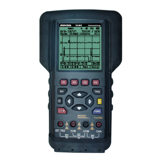
SERVICE MANUAL SCOPE METER S2480_E040404_R01... - Page 2 Programmable Handy Scope Series...
- Page 3 LIMITED WARRANTY & LIMITATION OF LIABILITY Each Seintek product is warranted to be free from defects in material and workmanship under normal use and service. The warranty period is one year and begins on the date of shipment. Parts, product repairs and services are warranted for 90 days.
-
Page 4: Table Of Contents
Contents Introduction and Specifications..........1-1 1.1. Main Features ............... 1-1 1.2. Unpacking the Test Tool Kit ........... 1-2 1.3. Specification ..............1-3 1.3.1. General Specifications ......... 1-3 1.3.2. Technical Specification......... 1-4 General Maintenance .............. 2-7 2.1. Introduction..............2-7 2.2. Warranty Repairs and Shipping Information ....2-7 2.3. - Page 5 5.3. How to Contact Seintek..........5-2 5.4. Newer Instruments ............5-2 5.5. Parts ................5-2 Schematic Diagrams ............... 6-1 6.1. S2401 & S2800 ............. 6-1 6.1.1. Main PCB Assembly ..........6-1 6.1.2. SUB PCB Assembly..........6-1 6.1.3. Analog..............6-1 6.1.4.
- Page 6 7.2. Troubleshooting guide........... 7-1 7.3. Starting with a Dead meter..........7-2 7.4. Can not install the software ........... 7-2 7.4.1. Check the H/W and S/W requirement:....7-2 7.4.2. Error - Could not copy file…........ 7-2 7.5. The back light is not working......... 7-3 7.5.1.
-
Page 7: Introduction And Specifications
Introduction and Specifications 1.1. Main Features This Programmable Universal Scope Meter offers enhanced features that similar type test instruments on the market today don't have. All the functions are designed to be very convenient to use. You can quickly get used to working with this METER and the great many functions integrated inside. -
Page 8: Unpacking The Test Tool Kit
Unpacking the Test Tool Kit The following items are included in your test tool kit. Note When new, the rechargeable Ni-MH battery pack is not fully charged. ■ STANDARD Description S2401 S2405 S2505 S2800 Scope Meter ● ● ● ●... -
Page 9: Specification
1.3. Specification 1.3.1. General Specifications 1) Operational Temperature: 0°C to +50°C (+32°F to +122°F) at a relative humidity 75% or less 2) Storage Temperature: -20°C to +60°C with a relative humidity of 75% less 3) Temperature Coefficient: 0.1 x (Specified Accuracy) per °C for temperature <18°C to >28°C 4) Max. -
Page 10: Technical Specification
1.3.2. Technical Specification 1) Oscilloscope Function (1) Horizontal 25 MS/s (Dual CH mode) Sample Rate 50 MS/s (Single CH mode) Record Length 512 single shot, 256 in all modes Sample / Division Modes Single shot, Roll, Normal Accuracy 0.01% Sweep Rate 1uS to 5S in 1, 2, 5 sequence (2) Vertical Bandwidth... - Page 11 2) Digital MultiMeter Function DC V Range Resolution Accuracy Impedance 0.001V ±(0.3%+3) 0.01V 1 MΩ 500V 0.1V ±(0.5%+5) 1000V AC V Accuracy Range Resolution Impedance 50~450Hz 0.45k~5kHz 5k~20kHz 0.001V ±(2.5%+5) 0.01V ±(0.75%+5) ±(2%+5) 1 MΩ 300V 0.1V 750V Range Resolution Accuracy Over Load Protection 5 kΩ...
- Page 12 The guaranteed range is below 5 MHz. RPM (S2401, S2405, S2505) Range Resolution Accuracy 240 - 60,000 1 RPM ±(0.05%+5) Pulse Width (S2401, S2405, S2505) Range 2uS-500mS (Pulse Width > 2uS) % Duty (S2401, S2405, S2505) Range 25% - 75% Only S2800 Function...
-
Page 13: General Maintenance
General Maintenance 2.1. Introduction This provides handling, cleaning, battery replacement, disassembly, and assembly instructions. 2.2. Warranty Repairs and Shipping Information If your meter is still under warranty, see the warranty information at the front of this manual for instructions on returning the unit. 2.3. -
Page 14: Disassembly Procedures
2.5. Disassembly Procedures The following paragraphs describe disassembly of the Meter in sequence (from the fully assembled meter to the Sub-assembly.) Start and end your disassembly at the appropriate heading levels. PC Cover Disassembly... - Page 15 Description Q’ty Top Case 1Pcs Rubber Button 1Pcs LCD Cover 1Pcs 1Pcs 1Pcs SUB PCB Assembly 1 Set Main PCB Assembly 1 Set Battery Pack 1Pcs Bottom Case 1Pcs Stand Top & Bottom 1Pcs S1 Screw for Top and Bottom case 3Pcs S2 Screw for Sub and Main PCB 4Pcs and 4Pcs...
-
Page 16: Remove The Meter Case
2.5.1. Remove the Meter Case Use the following procedure 3 PCS to remove the meter case. ① Power OFF Make sure the meter is turned off and unplugged from the power Adaptor. ② Remove Screw: Remove the three screw from the bottom of the case. -
Page 17: Separate Sub And Main Pcb Assembly
2.5.3. Separate SUB and Main PCB Assembly ① Remove Screw: Remove the four screw from the Sub PCB assembly. (4 Pcs) ② Separate PCB: The SUB PCB Assembly can now be lifted away from the Main PCB Assembly. 2.5.4. Remove LCD Cover ①... -
Page 18: Assembly Procedures
2.6. Assembly Procedures Generally, assembly procedures follow a reverse sequence of disassembly procedures. As some differences do apply, assembly is described separately in the following paragraphs. Begin assembly at the appropriate level, as defined by the heading. References are made to items in below Figure for assembly details of standard meter parts. -
Page 19: Layout For Scope Assembly
2.6.2. Layout for Scope Assembly PC Cover Assembly 2-13... -
Page 20: Performance Testing
Performance Testing 3.1. Introduction This chapter of the Service Manual provides performance tests that can be used at any time to verify the meter operation within published specifications. A complete calibration procedure is also included. The performance test and, if necessary, the calibration procedure can be performed periodically and after service or repair. -
Page 21: Dcv Tests
4. Verify scope center as changing V/DIV (0.5mV~500V) of CHA, B by pressing up and down arrow buttons. 3.3.2. DCV Tests 1. Press DIV button and change V/DIV to AUTO by pressing left or right arrow button. 2. Press F3 (H/DIV) button and change H/DIV to AUTO by pressing left or right arrow button. -
Page 22: Ohm Tests
1. Press FUNC button; then press F1 (Scope) button. 2. Select Hz of Measurements A;. then press F3, F4 and F4. 3. Apply AC 0.2Vrms/1MHz (S2401, S2800) or 0.2Vrms/5MHz (S2405, S2505) to equipment and verify that the measurement value is correct. -
Page 23: External Tests
3. Press TRIG button; then press F3 (Tmode) button. 4. Select EXT in Trigger SOURCE;. then press F3, F4 and F4. 5. Apply 1MHz (S2401, S2800) or 5MHz (S2405, S2505) to EXT.TRIG and COM connector and verify that the frequency measurement value is correct. -
Page 24: 3.3.11. Rs232 Input And Tests
3.3.11. RS232 Input and Tests 1. Verify that SETUP MENU, LOGO, SERIAL NO., etc is correct. 2. Verify the communication between equipment and computer by using RS232 program. -
Page 25: Calibration
Calibration 4.1. Introduction The adjustment procedure consists of several steps. Each step requires an external voltage source for new calibration constants. Before performing the adjustment procedure, you must warm up the instrument for at least ten minutes in an ambient temperature between 18˚C and 28˚C. -
Page 26: Entering Calibration Mode
4.3. Entering Calibration Mode ① With retaining buttons pressed, press button. ② Examine the screen status and buttons function. Key: Simultaneously. 4.4. Calibration Scope Center 1. Connect the tool for a short circuit test to CHA, CHB, and COM connector of the equipment. 2. -
Page 27: Calibration Zero Point Of Dmm Function
4.5. Calibration zero point of DMM function 1. Move to DMM function adjustment mode by pressing F4 (DMM) button. ① F/R: Function & Range- ② Z/cal: ZERO Calibration ③ R/cal: Reading Calibration ④ Tlvl: Trigger Level DMM Function Calibration Mode 2. -
Page 28: Ohms Calibration
1. Change to function ACV by pressing up or down arrow button. 2. Change to Range 200V by pressing left or right arrow button. 3. Apply AC 199.5V, 60Hz to equipment; Allow for settling; then press F3(R/cal) button. 4. Apply 20V, 2V, and 0.2V(S2405, S2505), 60Hz as described above. -
Page 29: List Of Replaceable Parts
5.2. How to Obtain Parts Electrical components may be ordered directly from the manufacturer by using the manufacturers part number, or from the Seintek and its authorized representatives by using the part number under the heading SEINTEK STOCK NO. Parts price information is available from the Seintek or its representatives. -
Page 30: How To Contact Seintek
5. Description (as given under the DESCRIPTION heading) 6. Quantity 5.3. How to Contact Seintek To contact Seintek, visit Seintek’s web site at www.seintek.com or call one of the following telephone numbers: Korea: +82-31-914-2381 5.4. Newer Instruments Changes and improvements made to the instrument are identified by incrementing the revision letter marked on the affected PCB. -
Page 31: Schematic Diagrams
Schematic Diagrams 6.1. S2401 & S2800 6.1.1. Main PCB Assembly 6.1.2. SUB PCB Assembly 6.1.3. Analog 6.1.4. Digital 6.1.5. Channel A 6.1.6. Channel B 6.2. S2405 & S2505 6.2.1. Main PCB Assembly 6.2.2. SUB PCB Assembly 6.2.3. Analog 6.2.4. Digital 6.2.5. -
Page 32: Troubleshooting
Troubleshooting 7.1. Introduction This chapter describes trobleshooting procedures than can be used to isolate problems with the meter. Warning Opening the case may expose hazardous voltages. Always disconnect the power cord and measuring inputs before opening the case. And remember that repairs or servicing should be performed only by qualified personnel. -
Page 33: Starting With A Dead Meter
If you set the trigger level to normal (NOR) mode, trigger level must be the same level of waveform. Meter does not trigger if trigger level set above or below waveform. If you set the trigger level to Auto (AT) mode, you do not need to control the trigger level. -
Page 34: The Back Light Is Not Working
7.5. The back light is not working When the back light is not working although the symbol is on the screen. To remove the Meter Case, refer to procedures chapter 2.5.1 to 2.5.3. 7.5.1. Desoldering from EL terminal ① Desoldering: Desoldering EL terminal (2 points). -
Page 35: Remove Lcd Cover
7.5.3. Remove LCD cover ① Remove LCD Cover: The LCD Cover can now be lifted away from the SUB PCB Assembly. "A" "A" 7.5.4. Detail for EL terminal ① EL terminal: After desoldering EL terminal VIEW "A" 7.5.5. Insert electric wire between PCB and EL ①... -
Page 36: Layout For Lcd Assembly
7.5.6. Layout for LCD Assembly ① Layout for LCD: LCD Cover, LCD, EL, LCD Cover Electric Wire (to be inserted) and PCB 1.6 x 12mm wire 7.5.7. Install LCD cover ① Caution Clean the LCD and Cover with deionized air and, if necessary, isopropyl alcohol. -
Page 37: Install Screw For Lcd Cover
7.5.8. Install screw for LCD cover ① Rotate the Sub PCB: Rotate the SUB PCB Assembly 180 degrees. ② Install Screw: Install the five screw for LCD cover 7.5.9. Soldering of EL terminal ① Rotate the Sub PCB: Rotate the SUB PCB Assembly 180 degrees. - Page 38 MEMO...
- Page 39 MEMO...
- Page 40 1332-5 Duggi-dong, Ilsan-gu, Koyang-city, Head Office Korea TEL: (82-31) 914-2381 Factory FAX: (82-31) 914-2385 Customer Services TEL: (82-31) 914-2384 Homepage http://www.seintek.com/ E-Mail seintek@seintek.com Sein Electronics Co., Ltd.
Need help?
Do you have a question about the S2401 and is the answer not in the manual?
Questions and answers