Sign In
Upload
Manuals
Brands
Seintek Manuals
Measuring Instruments
S2505
Seintek S2505 Manuals
Manuals and User Guides for Seintek S2505. We have
1
Seintek S2505 manual available for free PDF download: Service Manual
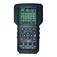
Seintek S2505 Service Manual (40 pages)
SCOPE METER
Brand:
Seintek
| Category:
Measuring Instruments
| Size: 1.29 MB
Table of Contents
Service Manual
1
Table of Contents
4
1 Introduction and Specifications
7
Main Features
7
Unpacking the Test Tool Kit
8
Specification
9
General Specifications
9
Technical Specification
10
2 General Maintenance
13
Introduction
13
Warranty Repairs and Shipping Information
13
Static Safe Handling
13
Cleaning
13
Disassembly Procedures
14
Remove the Meter Case
16
Remove Rubber Button and Battery Pack
16
Separate SUB and Main PCB Assembly
17
Remove LCD Cover
17
Assembly Procedures
18
Layout for LCD Assembly
18
Layout for Scope Assembly
19
3 Performance Testing
20
Introduction
20
Required Test Equipment
20
Performance Tests
20
Scope Center Tests
20
DCV Tests
21
ACV Tests
21
OHM Tests
22
Frequency Tests
22
AC/DC Coupling Tests
22
External Tests
23
CHB Tests
23
Duty Tests
23
3.3.10. Pulse Width Tests
23
3.3.11. RS232 Input and Tests
24
4 Calibration
25
Introduction
25
Preparation before Entering Calibration Mode
25
Voltage Test
25
Setting for RS232C
25
Entering Calibration Mode
26
Calibration Scope Center
26
Calibration Zero Point of DMM Function
27
DC Volts Calibration
27
AC Volts Calibration
27
Ohms Calibration
28
Frequency Calibration
28
Exiting Calibration Mode
28
5 List of Replaceable Parts
29
Introduction
29
How to Obtain Parts
29
How to Contact Seintek
30
Newer Instruments
30
Parts
30
6 Schematic Diagrams
31
S2401 & S2800
31
Main PCB Assembly
31
SUB PCB Assembly
31
Analog
31
Digital
31
Channel a
31
Channel B
31
S2405 & S2505
31
7 Troubleshooting
32
Introduction
32
Troubleshooting Guide
32
Starting with a Dead Meter
33
Can Not Install the Software
33
Check the H/W and S/W Requirement
33
Error - Could Not Copy File
33
The Back Light Is Not Working
34
Desoldering from el Terminal
34
Remove Screw for LCD Cover
34
Remove LCD Cover
35
Detail for el Terminal
35
Insert Electric Wire between PCB and el
35
Layout for LCD Assembly
36
Install LCD Cover
36
Install Screw for LCD Cover
37
Soldering of el Terminal
37
7.5.10. Reassembly
37
Advertisement
Advertisement
Related Products
Seintek S2405
Seintek S2401
Seintek S2800
Seintek Categories
Measuring Instruments
More Seintek Manuals
Login
Sign In
OR
Sign in with Facebook
Sign in with Google
Upload manual
Upload from disk
Upload from URL