Viessmann vitocrossal 300 Installation Instructions Manual
Gas fired condensing boiler
Hide thumbs
Also See for vitocrossal 300:
- Service instructions manual (164 pages) ,
- Service instructions for contractors (148 pages) ,
- Service manual (108 pages)

Related Manuals for Viessmann vitocrossal 300


Summary of Contents for Viessmann vitocrossal 300
-
Page 1: Installation Instructions
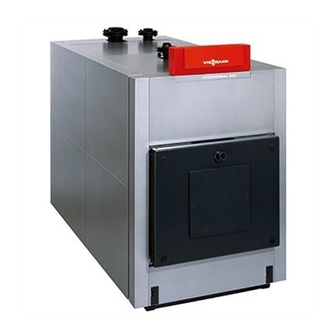
VIESMANN Installation instructions for contractors Vitocrossal 300 Type CR3 and CR37 Gas fired condensing boiler Rated output 787 and 978 kW VITOCROSSAL 300 Dispose after installation. 5862 299 GB 11/2009... -
Page 2: Safety Instructions
Safety instructions Please follow these safety instructions closely to prevent accidents and mate- rial losses. Safety instructions explained ■ the Code of Practice of relevant trade associations, Danger ■ all current safety regulations as This symbol warns against the defined by DIN, EN, DVGW, TRGI, risk of injury. -
Page 3: Table Of Contents
Index Preparing for installation................... Installation sequence Boiler positioning and levelling................■ Installation with anti-vibration boiler supports........... ■ Installation without anti-vibration boiler supports..........Assembly when supplied in sections..............Fitting the feet to the heat exchanger module............Flue gas connection..................... Fitting the thermal insulation................10 ■... -
Page 4: Preparing For Installation
Preparing for installation Clearance dimensions Note You can reposition the hinge bolts so that the door opens to the left. 200 (100) 500 (50) 500 (50) (300) A Boiler C Anti-vibration boiler supports B Burner Dimensions in brackets are minimum clearances. - Page 5 Preparing for installation (cont.) Rated output 1500 1500 Observe the burner length Anti-vibration boiler supports Permissible load 3000 c (front) / number mm/pce 750/2 c (back) / number mm/pce 750/2 e (without stress) e (stressed)
-
Page 6: Boiler Positioning And Levelling
Boiler positioning and levelling Installation with anti-vibration boiler supports Ensure the boiler foundation is level. Position the boiler onto the anti-vibration boiler supports. Continue on page 7 or 9. Installation without anti-vibration boiler supports 1. Insert the adjustable screws into the 2. -
Page 7: Assembly When Supplied In Sections
Assembly when supplied in sections A Heat exchanger module C Sealant (in the pack supplied) B Combustion chamber module D Gaskets (in the pack supplied) - Page 8 Assembly when supplied in sections (cont.) Please note 5. Check that there is sufficient sealant Scratches on parts that are in all around the sealing face of the contact with flue gas can lead to combustion chamber. corrosion. Close any gaps between the com- Never put tools or other objects bustion chamber module and the into the combustion chamber.
-
Page 9: Fitting The Feet To The Heat Exchanger Module
Fitting the feet to the heat exchanger module 1. Wind the anti-vibration feet in as far as possible. 2. Secure the feet with two screws each to the l.h. and r.h. side of the heat exchanger using the top holes. 3. -
Page 10: Fitting The Thermal Insulation
Fitting the thermal insulation Boiler body thermal insulation Note Before fitting the thermal insulation, check the serial number on the type plate and compare it with the serial number stamped on the front of the boiler. If the boiler is supplied in sections,two type plates will be included. -
Page 11: Front Thermal Insulation
Fitting the thermal insulation (cont.) Front thermal insulation Front rails... -
Page 12: Back Rails
Fitting the thermal insulation (cont.) Back rails Note Do not tighten the wing screws yet. -
Page 13: Centre Rails
Fitting the thermal insulation (cont.) Centre rails 1. Secure the wing screws to the top 4. If necessary, align the rails so that the and bottom boiler rails. gap between both side panels runs parallel. 2. Hook the centre rail into the wing screws and loosely tighten by hand. -
Page 14: Routing Burner Cables
Fitting the thermal insulation (cont.) Routing burner cables lÖ Side panels and back rails Note Secure the rails after alignment. -
Page 15: Rear Thermal Insulation
Fitting the thermal insulation (cont.) Rear thermal insulation... -
Page 16: Rear Panels
Fitting the thermal insulation (cont.) Rear panels... -
Page 17: Front Panels
Fitting the thermal insulation (cont.) Front panels... -
Page 18: Preparing The Control Unit Installation
Fitting the thermal insulation (cont.) Preparing the control unit installation B 3.9 x 30 A Boiler coding card (part of boiler accessories) Note Please note Boiler water temperature sensor § is Damaged capillary tubes result in incorrect sensor functions. included with the control unit. Insert the Never kink the capillary tubes. - Page 19 Fitting the thermal insulation (cont.) § A Strain relief Pull all external cables through the aper- Note tures in the back and front walls into the Set the high limit safety cut-out to a max- control unit wiring chamber. imum of 110 ºC. Installation instructions, boiler Installation and service instruc- control unit...
-
Page 20: Fitting The Top Panels
Fitting the thermal insulation (cont.) Fitting the top panels B 3.9 x 30 Note Remove the bottom section (with bar- Affix the type plate in an accessible place code) from the smaller type plate of the to the front of the side panel. heat exchanger module and affix it to the section provided in the centre of the Only when supplied in sections:... -
Page 21: Connecting The Heating Water Side
Connecting the heating water side A Boiler return 2: PN 6 DN 100 F Boiler flow: PN 6 DN 125 B Boiler return 1: PN 6 DN 125 G Fem. connections for control equip- ment: R ½" C Fem. connection for maximum pres- H Condensate drain: R ½"... -
Page 22: Making The Safety Connections
Connecting the heating water side (cont.) Danger Please note Leaking heating water may Unsuitable water qualities can cause injuries. result in boiler body damage. Only open the connections on the Only fill the boiler with water that heating water side after the boiler complies with the "Water quality has been de-pressurised. -
Page 23: Stench Trap Installation
Making the safety connections (cont.) Safety valve Note Install all pipe connections free of load Equip boilers with a safety valve which is and torque stresses. type-tested according to TRD 721 and must be marked in accordance with the relevant system version. Stench trap installation 1. -
Page 24: Connection Of The Neutralising System
Connection of the neutralising system Neutralising system installation instructions 1. Install the neutralising system either behind or next to the boiler. 2. Trim the plastic hose supplied to the required size and connect it to the stench trap and to the neutralising system. -
Page 25: Installing The Combustion Chamber Sight Glass
Installing the combustion chamber sight glass Install the combustion chamber sight glass. Connect the sight glass with the pressure-jet part of the burner (test port for "static burner pressure") using the plastic hose supplied. Adjust burner For burner adjustments, see the Note separate burner documentation. - Page 28 Viessmann Werke GmbH&Co KG Viessmann Limited D-35107 Allendorf Hortonwood 30, Telford Telephone: +49 6452 70-0 Shropshire, TF1 7YP, GB Fax: +49 6452 70-2780 Telephone: +44 1952 675000 www.viessmann.com Fax: +44 1952 675040 E-mail: info-uk@viessmann.com...
Need help?
Do you have a question about the vitocrossal 300 and is the answer not in the manual?
Questions and answers