
Related Manuals for Riello SDH 1000 UL


Summary of Contents for Riello SDH 1000 UL
- Page 1 User & Operations Manual Sentinel DUAL UL True-Online UPS System 1000 VA -1500 VA - 2000 VA - 3000 VA...
- Page 2 NTRODUCTION Congratulations on purchasing a UPS Sentinel Dual product and welcome to Riello UPS! To use the support service offered by Riello UPS, visit the site www.riello-ups.com Our Company is a specialist in the design, development and manufacturing of uninterruptible power supplies (UPS).
-
Page 3: Table Of Contents
ONTENTS PRESENTATION UPS V IEWS RONT VIEW EAR VIEW ISPLAY PANEL VIEW ATTERY ACCESSORY NOT SUPPLIED WITH THE UPS EAR VIEW INSTALLATION NITIAL CONTENT CHECK NSTALLATION ENVIRONMENT ATTERY OX INSTALLATION ETTING THE NOMINAL BATTERY CAPACITY OWER VERSION OWER VERSION WITH BATTERY BOX ACK VERSION ONNECTIONS AND SWITCHING ON FOR THE FIRST TIME WITCHING ON FROM THE MAINS... - Page 4 OMMUNICATION ATTERY PACK REPLACEMENT TROUBLESHOOTING LARM CODES AULT TECHNICAL DATA...
-
Page 5: Presentation
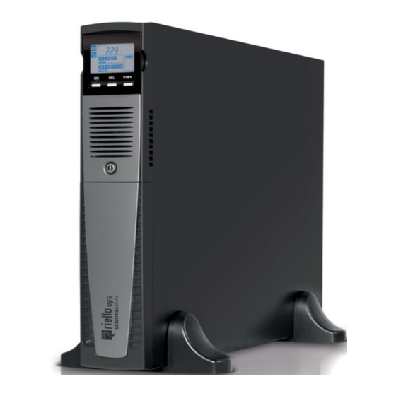
PRESENTATION SENTINEL DUAL uses ON-LINE double conversion technology, resulting in the highest levels of reliability and maximum protection for critical loads such as servers, IT applications and Voice/Data. This family was designed with versatility in mind, allowing for installation in both tower and rack positions. The following shows how the product can be installed in the two different positions: The UPS is also equipped with a dedicated battery pack that allows for easy battery replacement (hot swap) in complete safety thanks to the protected connection system. -
Page 6: Ups Views
UPS V IEWS RONT VIEW Extractable/rotatable display plate Removable front panel Release slits Battery pack connector ON/OFF Switch Battery pack retention panel... -
Page 7: Rear View
EAR VIEW Model 1000VA / 1500VA Model 2000VA Model 3000VA Communication port RS232 Battery expansion connector (optional) USB communication port NEMA 10A output socket NEMA 16A output socket NEMA 16A input plug Communication Card Slots NEMA 10A input plug Cooling fans Circuit breaker Remote control terminal board... -
Page 8: Display Panel View
ISPLAY PANEL VIEW “SEL” button (Select) Load level indicator “ON” button Configuration area “STAND-BY” button Maintenance request Regular operation Timer Mains operation Measurement display area Battery operation Stand-by / alarm Load powered by bypass EnergyShare Battery charge indicator... -
Page 9: Battery Box ( Accessory Not Supplied With The Ups )
ATTERY ACCESSORY NOT SUPPLIED WITH THE UPS The BATTERY BOX is an optional accessory for this range of UPS (same dimensions and aesthetic appearance). The BATTERY BOX contains batteries which allow the operating time of the uninterruptible power supplies to be increased during extended blackouts. -
Page 10: Installation
INSTALLATION NITIAL CONTENT CHECK After opening the packaging, it is first necessary to check the contents. The package must contain: Support feet USB cable RS232 cable User manual CD + Safety manual Handles for rack installation Handle screws Battery expansion plug... -
Page 11: Installation Environment
NSTALLATION ENVIRONMENT The UPS and the Battery Box must be installed in ventilated, clean environments which are sheltered from bad weather. The relative humidity in the environment must not exceed the maximum values shown in the Technical Data table. The ambient temperature, whilst the UPS is in operation, must remain between 0 and 40°C, and the UPS must not be positioned in places which are exposed to direct sunlight or to hot air. -
Page 12: Tower Version
OWER VERSION This chapter describes the steps for preparing the UPS and battery box for tower version use. ATTENTION: For your safety and that of the product, you must carefully follow the instructions given here below. BEFORE YOU CARRY OUT THE FOLLOWING SEQUENCE OF OPERATIONS, MAKE SURE THAT THE UPS IS COMPLETELY SWITCHED OFF AND NOT CONNECTED TO THE MAINS POWER SUPPLY OR TO ANY LOAD Once removed from the packaging, the UPS is already preset for installation in the tower configuration. -
Page 13: Tower Version With Battery Box
OWER VERSION WITH BATTERY BOX BEFORE CARRING OUT THE FOLLOWING SEQUENCE OF OPERATIONS, ENSURE THAT: THE UPS IS COMPLETELY SWITCHED OFF AND NOT CONNECTED TO THE MAINS POWER SUPPLY OR TO ANY LOAD. THE BATTERY BOX IS DISCONNECTED FROM THE UPS, FROM ANY OTHER BATTERY BOXES AND WITH THE BATTERY ISOLATOR OPEN ... -
Page 14: Rack Version
ACK VERSION The sequence of operations to be followed in order to transform the UPS or battery box into rack version are described below. BEFORE CARRING OUT THE FOLLOWING SEQUENCE OF OPERATIONS, ENSURE THAT: THE UPS IS COMPLETELY SWITCHED OFF AND NOT CONNECTED TO THE MAINS POWER SUPPLY OR TO ANY LOAD. -
Page 15: Use
ONNECTIONS AND SWITCHING ON FOR THE FIRST TIME 1) Check that there is a protection device against overcurrents and short circuits in the system upstream from the UPS. The recommended protection value is 15A (for the 1000VA and 1500VA versions), 20A (for the 2000VA version) and 30A (for the 3000VA version) with a B or C trip curve. -
Page 16: Display Panel Messages
ISPLAY PANEL MESSAGES This chapter describes, in detail, the various information that can be displayed on the LCD. STATUS MESSAGES ICON STATUS DESCRIPTION Fixed Indicates a fault Flashing The UPS is in stand-by mode Fixed Indicates regular operation Fixed The UPS is operating from the mains The UPS is operating from the mains, but the output voltage is not Flashing synchronized with the mains voltage... -
Page 17: Measurement Display Area
EASUREMENT DISPLAY AREA It is possible to display the most important measurements regarding the UPS in sequence on the display. When the UPS is switched-on, the display shows the main voltage value. To display a different measurement, press the “SEL” button repeatedly until the desired measurement appears. In the event of a fault/alarm (FAULT) or a lock (LOCK), the display will automatically show the type and code of the corresponding alarm. -
Page 18: Onfiguring The Ups Parameters
UPS PARAMETERS ONFIGURING THE The area of the display shown in the figure displays the setting interface and allows the user to configure some UPS parameters directly from the display panel. HOW TO PROCEED: To enter the setting mode, hold down the “SEL” button for at least 3 seconds when the UPS is in STANDBY-BY mode. - Page 19 03: Output frequency setting Interface Setting Parameter 2: Output frequency setting. 50: presents output frequency is 50Hz 60: presents output frequency is 60Hz 04: ECO enable/disable Interface Setting Parameter 2: Enable or disable ECO function. You may choose the following two options: ENA: ECO mode enable DIS: ECO mode disable (Default)
- Page 20 08: Autonomy limitation setting Interface Setting Parameter 2: Set up backup time on battery mode for general outlets. 0-999: setting the backup time in minutes from 0-999 for general outlets on battery mode. DIS: Disable the autonomy limitation and the backup time will depend on battery capacity.
-
Page 21: Additional Functions
DDITIONAL FUNCTIONS MANUAL BYPASS Using the Manual Bypass feature, the UPS can be switched to bypass. In this condition the load is powered directly by the input mains, any disruption in the mains directly affects the load. CAUTION: BEFORE CARRYING OUT THE FOLLOWING SEQUENCE OF OPERATIONS, ENSURE THAT THE UPS’S INPUT AND OUTPUT FREQUENCY COINCIDE AND THAT THE UPS IS NOT OPERATING FROM THE BATTERY Attention: even when the UPS is switched on, the load is disconnected in the event of a mains blackout. -
Page 22: Software
OFTWARE ONITORING AND CONTROL SOFTWARE The ViewPower software guarantees effective, intuitive UPS management, displaying all the most important information such as input voltage, applied load and battery capacity. It is also able to perform shutdown operations and send e-mails, text messages and network messages automatically when certain events, selected by the user, occur. -
Page 23: Ups Configuration
CONFIGURATION The table below illustrates all the possible configurations available to the user in order to best adapt the UPS to individual requirements. It is possible to perform these operations using the LCD setting and ViewPower software. FUNCTION DESCRIPTION DEFAULT POSSIBLE CONFIGURATIONS Selects the nominal output Output voltage... - Page 24 FUNCTION DESCRIPTION DEFAULT POSSIBLE CONFIGURATIONS Enabled Alarm at battery Alarm at battery mode Enabled Disabled mode enable or disable Enabled Auto reboot enable or Auto reboot Enabled Disabled disable Enabled Green power Green power function Disabled function enable or disable...
-
Page 25: Communication Ports
(see figure on right) which allows the device to communicate using the main communication standards. Some examples: Ethernet network card with TCP/IP, HTTP and SNMP protocols MODBUS protocol converter card Card with relay isolated contacts To check the availability of other accessories, visit the website www.riello-ups.com. -
Page 26: B Attery Pack Replacement
ATTERY PACK REPLACEMENT The UPS is also equipped with a dedicated battery pack that allows for easy replacement of batteries (hot swap) in complete safety, thanks to the protected connection system. WHEN THE BATTERY PACK IS DISCONNECTED, THE LOADS CONNECTED TO THE UPS ARE NOT PROTECTED IN THE EVENT OF A MAINS FAILURE ... - Page 27 Remove the battery pack's retention panel carrying out the operations shown in the figure below. Slip off the battery pack pulling it towards the outside, as shown in the figure below. Be careful when extracting and lifting up the battery pack as it is heavy.. ATTENTION: the new battery pack must contain the same number and type of batteries (see the label located on the battery pack near the connector).
-
Page 28: Troubleshooting
TROUBLESHOOTING Irregular UPS operation is most likely not an indication of a fault but due to simple problems or distraction. It is therefore advisable to consult the table below carefully as it summarizes information which is useful for solving the most common problems. - Page 29 The UPS in case of a permanent failure will be not able to supply the load. To ensure total protection of your equipment we suggest you install an ATS device (Automatic Transfer Switch) or an external automatic by-pass. For more information visit www.riello-ups.com...
-
Page 30: A Larm Codes
LARM CODES Using a sophisticated self-diagnosis system, the UPS is able to check its own status and any anomalies and/or faults which may occur during normal operation and display them on the display panel. If there is a problem, the UPS signals the event by showing the code and the type of active alarm on the display (FAULT and/or LOCK). - Page 31 Active commands: Indicates the presence of an active remote command. CODE DESCRIPTION Emergency power off load on bypass or manual bypass command Battery test in progress LOCK alerts are normally preceded by an alarm signal and their scale leads to the power-off of the inverter and the load being powered by the bypass line (this procedure is excluded for locks due to serious, persistent overloads and short circuits).
-
Page 32: Technical Data
TECHNICAL DATA UPS MODELS SDH 1000 UL SDH 1500 UL SDH 2000 UL SDH 3000 UL INPUT Nominal voltage [Vac] 100 / 110 / 115 / 120 / 127 Maximum operating voltage [Vac] Nominal frequency [Hz] 50/60 Rated current (1) 13.2... - Page 33 20 - 25 °C / 68 – 77 °F for longer battery life Output Power Rating Table Model name Input rating Output rating 110-127Vac, 50/60Hz, 100/110/115/120/125/127Vac, 50/60Hz, SDH 1000 UL 12A, 1Ø 1000VA/1000W, 1Ø, 10A 110-127Vac, 50/60Hz, 100/110/115/120/125/127Vac, 50/60Hz, 1Ø SDH 1500 UL 12A, 1Ø...
Need help?
Do you have a question about the SDH 1000 UL and is the answer not in the manual?
Questions and answers
How to keep ups on bypass mode
To keep the Riello SDH 1000 UL UPS in bypass mode, follow these steps:
1. Ensure the UPS’s input and output frequency coincide and that it is not operating from the battery.
2. Press and hold the ON and SEL keys simultaneously for at least 4 seconds.
3. The code "C02" will appear on the display, indicating that the UPS is in bypass mode.
In bypass mode, the load is powered directly by the input mains, and any disruptions in the mains will directly affect the load.
This answer is automatically generated