Table of Contents
Advertisement
Quick Links
Advertisement
Table of Contents

Related Manuals for Merrychef MicroaireRMC1003


Summary of Contents for Merrychef MicroaireRMC1003
- Page 1 M i c r o a i r e S E R V I C E M A N U A L For all Microaire models manufactured from January 2001 Part No. 32Z3311e Issue No. 6 CAUTION MICROWAVE EMISSIONS DO NOT BECOME EXPOSED TO EMISSIONS FROM THE MICROWAVE GENERATOR OR PARTS CONDUCTING MICROWAVE ENERGY Microaire Ovens 32Z3311e Issue 5 Page 1...
-
Page 2: Table Of Contents
Electrical Diagram - RMC1003RS RF / HST ....... 31 Merrychef Limited, Station Road West, Ash Vale, Aldershot Hampshire GU12 5XA United Kingdom Tel: +44 (0)1252 371000 Fax: +44 (0)1252 371007 Internet address: http://www.merrychef.co.uk E-mail: sales@merrychef.co.uk or service@merrychef.co.uk Microaire Ovens 32Z3311e Issue 5 Page 2... -
Page 3: Safety Code
This manual is designed to assist engineers who have been on a recognised product familiarisation and training course run by Merrychef Limited. It has been prepared to offer technical guidance for the Merrychef Microaire Series 5 range of Combination Microwave Ovens. -
Page 4: Product Specifications
PRODUCT SPECIFICATIONS ELECTRONIC CONTROLS Model Number: RMC1003 + Voltage + Frequency + Current + Controls + Extras Model prefix Voltage Frequency Current Control Type 2 = 220-230V a.c. 5 = 50 Hz EE=Reduced Cur- 5 = Series 5 RMC1003 4 = 230-240V a.c 6 = 60 Hz rent controls... -
Page 5: Principles Of Operation
Microaire Ovens 32Z3311e Issue 5 Page 5... -
Page 6: Installation Instructions
INSTALLATION INSTRUCTIONS Power Supply Requirements The Microaire Series should be connected to a suitable electricity supply, which can cope with the switching-on surge that occurs with certain types of catering equipment, such as microwaves. Because of this requirement, we strongly recommend that a separate, suitably rated supply is installed for the oven. -
Page 7: Error Codes And Diagnostics
Error Codes and Diagnostics The Microaire Series 5 will identify some of the most common problems by flashing an error message code in the time display window. These are the error messages, and suggestions for repairing them. Door not fully shut. Close door fully. -
Page 8: Main Features
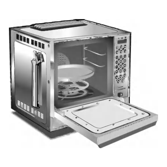
Main Features h TURNTABLE TRAY a STEAM OUTLET The vitreous enamelled turntable tray fits onto Allows steam and excess pressure to escape the turntable disc in the bottom of the oven from the oven cavity. It must be kept clear. cavity, and rotates during cooking to ensure an b AIR OUTLET even distribution of microwave energy. -
Page 9: Electronic Controls
Electronic controls: Microaire Series 5 Stage LED's Service Indicator Air Filter Block Indicator Operator error indicator Program Display Temperature Set Pads Time / Precept Pads Cancel/ Callback Pad Program Pad Convection Pad Microwave power Pads On/Off switch (Ref. No. 97) Microaire Ovens 32Z3311e Issue 5 Page 9... -
Page 10: Manual Controls
Manual controls: Model No.s CD2, XD2 Timer Amber Neon Control Knob Start Pushbutton Cook cycle Red Neon Power Amber Neon On/Off switch Microaire Ovens 32Z3311e Issue 5 Page 10... -
Page 11: A - Power Output Testing To En 60335-2-90:1996
Procedure A - Power Output Test in accordance with BS EN 60335-2-25:1996 Annex AA This test is given in the BSI test standard for microwave ovens. It is reproduced below - not so that you can follow it, but to show you why it is impractical in normal conditions. A simplified procedure, which gives a good approximation to the BSI power output, is given in Procedure B which follows. -
Page 12: B - Power Output Testing
Procedure B - Simplified Power Test You will need: A thermometer capable of reading to ±0.1°C. A Polypropylene tray approximately 200 mm x 200 mm. A measuring jug. A calculator. Water which is at a temperature of 10°C ± 2°C. Measure 1 litre of cold water into the tray using the measuring jug. -
Page 13: D - High Voltage Capacitor Test
Procedure D - High Voltage Capacitor Test You will need: A Digital Multi-meter (D.M.M.) A Megger or similar resistance meter using 500V d.c. WARNING: High voltages and large currents are present at the High Voltage Capacitor. It is very dangerous to work near this part when the oven is on. NEVER make any voltage measurements at the High Voltage circuits, including the magnetron filament . -
Page 14: Diagram - Casework
Principal components: Casework Side Panel (L/H) MC3134 Grease Filter MC3155 Ferrite (2) RMC6773 Side Panel (R/H) MC3133 Upper Trim MC3120X01 Handle Hanger (2) RCK6319 Top Plate RMC6759E Rubber Foot (EE,XE) (4) RMC6104 Foot (RF, HST) (4) 40H0092 Exhaust Gallery RMC73372 Front Lower Panel MC3047 Rear Panel... -
Page 15: Diagram - Door Mechanism
Door Mechanism Door Stay (R/H) MC3040 Hinge Body MC30121 Hook (A) RMC66171 Hook (B) RMC66172 Door Spring (B) MC3068X01 Hinge Body (L/H) MC30122 Door Spring (A) MC3067 Door Stay (L/H) MC3046 Microswitch Guide 40H0076 Microaire Solid Door Assy 11H0031 Microaire Ovens 32Z3311e Issue 5 Page 15... -
Page 16: Oven Cavity Components & Hot Air System
Oven Cavity Components and Hot Air System Turntable Disc RMC7340X01 31 Gearbox MC3216 Baffle Plate Bolt CP30326 32 Shaft RMC7391X01 Baffle Plate MC3018 33 Cooling Fan RMC7310 Fan Fixing Cap RCK7617 34 Motor Bracket RMC7307X01 MC3111 35 Cushion Rubber RCK8273 Partition Plate 11H0007 36 Motor Fixing Screw... -
Page 17: Oven Door Assembly
Oven Door Assembly Black Handle Microaire RBR12852 Door Frame (A) Black MC30503 Door Cover Outer Skin 40H0080 Insulation Panel 40H0081 Door Reinforcement RMC70722 Door Frame (B) MC3055 Insulation Wrap 32Z0001 Window Screen 40H0082 Door Base Silver MC3031KX04 Door Cover MC3064 Plate - Door Switch MC3056 Screen... -
Page 18: Magnetron & Door Interlock Components
Magnetron and Door Interlock Components 54 Door Switch Bracket Ass 11H0033 62 Inlet Duct RMC7193X01 Primary Microswitch 30Z0240 63 Magnetron 30Z0264 Low Voltage Microswitch 30Z0240 64 Magnetron Cut-out 30Z0088 Secondary Microswitch 30Z0240 Monitor Microswitch 30Z0240 65 Switch Bracket RMC7100X01 59 Microswitch Insulator 31Z0115 66 Blower Assembly MC3141... -
Page 19: F - Interlock Operation
Door Interlock Operation The door on the Microaire Series 5 oven is monitored by four microswitches. Three of these are used in the conventional “Primary, Secondary and Monitor” switch arrangement shown below, while the fourth is a low-voltage switch linked directly to the control circuitry. The switches operate as follows: Door Interlock Arrangement Power In... -
Page 20: Major Electrical Components
Major Electrical Components All Variants RMC100345 EE/XE 5 Microaire Ovens 32Z3311e Issue 5 Page 20... - Page 21 RMC100345 RS RF RMC100345 RS HST 69 Cavity Overheat Switch 30Z1031 79 Fuse Cover 20Z1080 80 Fuse 10A HRC 30Z0217 70 Bridge Rectifier (EE only) 341520 81 Fuse Holder 1” 30Z0231 71 N0. 8 Screw 31Z3107 82 Fuse 13A Anti-surge 30Z0168 64 Magnetron Overheat Switch 30Z0088...
- Page 22 Input Wiring Details: Microaire Series 5 EE5 Green / Yellow Blue Brown Input Wiring Details: Microaire Series 5 XE5 Green / Yellow Blue Brown 111 Mains Input Block 31Z0328 112 Cable Gland 31Z1070 113 Input Cable Assembly 31Z0220 115 XE5 Input Cable Assembly 302030 116 Strain Relief Grommet 31Z1036...
-
Page 23: Input Wiring Details
Input Wiring Details: Microaire Series 5 RS RF Black Brown Green / Yellow Black Blue Input Wiring Details: Microaire Series 5 RS HST Black Black Brown Green / Yellow Blue Fuse 10A HRC 30Z0217 Fuse 13A Anti-surge 30Z0168 Fuse 16A 1¼” 30Z1066 Cable Gland 31Z1070... -
Page 24: Ht Components
HT Components 88 HT Transformer Top Bracket MC3127 89 HV Lead Assembly 11H0025 75 HV Diode Assembly 11H0010 90 Unitran HT Transformer 240V 30Z0992 Unitran HT Transformer 220V 30Z1018 91 HT Transformer Bottom Bracket 40H0070 76 HT Capacitor 30Z0989 92 Capacitor Band RMC7215 93 Filter Bracket 40H0065... -
Page 25: Electronic Control Panel Assembly
Electronic Control Panel Assembly: Microaire Series 5 95 Membrane Assembly 11H0024 103 Microaire S5 Relay Assy. 11C0286 Microaire S5 RS Relay Assy. 11H0028 96 Microaire 5 Extrusion LH 40H0083 104 Microaire 5 Extrusion RH 40H0084 97 On/Off Switch 30Z0503 105 Side Trim MC31211 98 Microaire S5 Logic Assy. -
Page 26: Manual Controls Panel Assembly
Manual Control Panel Assembly: Microaire CD2, XD2 123A 123B 123C 123D On/Off Switch 30Z0503 PCB Assembly 11H0027 Timer 30Z0991 Amber Neon 316031 124A Control Knob 313020 124B Control Knob Skirt 313160 124C Control Knob Cap 313220 124D Control Knob Shaft Adaptor 313030 Pushbutton (Start) 31Z0349... -
Page 27: Membrane Panel Circuit
Membrane Panel Circuit: Microaire Series 5 You will need: A Digital Multi-meter (D.M.M.) 1. Isolate the oven from the mains supply. 2. Remove the Logic Assembly from the Control Panel Housing. 3. Unplug the membrane “tail” from the Logic PCB Assy. 4. -
Page 28: Complete Spare Part Listing
Part Number Identification Chart: Microaire series ovens SIDE PANEL (L/H) MC3134 INSULATION WRAP 32Z0001 FERRITE (2) RMC6773 WINDOW SCREEN 40H0082 UPPER TRIM MC3120X01 DOOR BASE SILVER MC3031KX04 TOP PLATE RMC6759E DOOR COVER MC3064 EXHAUST GALLERY RMC73372 PLATE - DOOR SWITCH MC3056 REAR PANEL MC3129... - Page 29 Part Number Identification Chart: Microaire series ovens FUSE 16A 1¼” 30Z1066 MICROAIRE 5 EXTRUSION RH 40H0084 FUSE HOLDER 1¼” 30Z0285 SIDE TRIM MC31211 HT TRANSFORMER TOP MC3127 M5 FLAT WASHER 31Z5004 BRACKET PCB STAND-OFF 31Z7010 HV LEAD ASSEMBLY 11H0025 15 WAY RIBBON CONNECTOR 11Z0298 UNITRAN HT TRANSFORMER 30Z0992...
-
Page 30: Electrical Diagram - Rmc1003Xxee5 / Xe5
Circuit Diagram: Series 5 EE & XE Microaire Ovens 32Z3311e Issue 5 Page 30... -
Page 31: Electrical Diagram - Rmc1003Rs Rf / Hst
Circuit Diagram: Series 5 RS Microaire Ovens 32Z3311e Issue 5 Page 31... -
Page 32: Station Road West
Address Page on which error occurs (if applicable) - Microaire Series Description of error Suggestion for improvement to manual Please return this form to: Engineering Department Merrychef Ltd Station Road West Ash Vale Aldershot Hampshire GU12 5XA Or Fax it on:...
Need help?
Do you have a question about the MicroaireRMC1003 and is the answer not in the manual?
Questions and answers