Mitsubishi Electric Mr.SLIM PE-3EAK Technical & Service Manual
Ceiling concealed
Hide thumbs
Also See for Mr.SLIM PE-3EAK:
- Operation manual (52 pages) ,
- Installation manual (32 pages)
Table of Contents
Advertisement
SPLIT-TYPE, AIR CONDITIONERS
TECHNICAL & SERVICE MANUAL
Ceiling Concealed
Series PE
<Indoor unit>
[Model names]
PE-3EAK
PE-4EAK
PE-5EAK
PE-6EAK
NOTE:
• This service manual describes technical data of indoor units.
• RoHS compliant products have <G> mark on the spec name plate.
[Service Ref.]
PE-3EAK.TH
PE-3EAK.TH-U
PE-4EAK.TH
PE-4EAK.TH-U
PE-5EAK.TH
PE-5EAK.TH-U
PE-6EAK.TH
PE-6EAK.TH-U
TEMP.
ON/OFF
This manual does not cover
outdoor units.
When servicing them, please
refer to the service manual
No. OC152, OC206, OC353
and this manual in a set.
CONTENTS
1. PART NAMES AND FUNCTIONS··········2
2. SPECIFICATIONS ··································4
3. DATA·······················································7
4. OUTLINES AND DIMENSIONS ···········16
5. WIRING DIAGRAM·······························20
6. REFRIGERANT SYSTEM DIAGRAM ········21
7. TROUBLESHOOTING··························23
8. FUNCTION SETTING ···························36
9. SYSTEM CONTROL·····························42
10. DISASSEMBLY PROCEDURE·············56
11. RoHS PARTS LIST·······························58
12. OPTIONAL PARTS·······························62
May 2006
No. OC394
Advertisement
Table of Contents
Troubleshooting

Subscribe to Our Youtube Channel
Related Manuals for Mitsubishi Electric Mr.SLIM PE-3EAK


Summary of Contents for Mitsubishi Electric Mr.SLIM PE-3EAK
- Page 1 SPLIT-TYPE, AIR CONDITIONERS May 2006 No. OC394 TECHNICAL & SERVICE MANUAL Ceiling Concealed Series PE This manual does not cover outdoor units. <Indoor unit> When servicing them, please refer to the service manual [Model names] [Service Ref.] No. OC152, OC206, OC353 PE-3EAK.TH and this manual in a set.
-
Page 2: Part Names And Functions
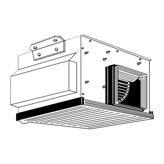
PART NAMES AND FUNCTIONS Indoor (Main) Unit Air intake duct flange Air intake (sucks the air inside the room into the unit) Air outlet Air outlet duct flange Remote controller Once the controls are set, the same operation mode can be repeated by simply pressing the ON/OFF button. Operation buttons ON/OFF button Set Temperature buttons... - Page 3 Display “Sensor” indication Displayed when the remote controller sensor is used. Day-of-Week For purposes of this explanation, Shows the current day of the week. all parts of the display are shown as lit. During actual operation, only Time/Timer Display the relevant items will be lit. “Locked”...
-
Page 4: Specifications
SPECIFICATIONS 2-1 STANDARD SPECIFICATIONS Service Ref. PE-3EAK.TH(-U) PE-4EAK.TH(-U) Item 7,500 9,800 50Hz Btu/h 25,600 33,400 Cooling capacity W1 8,100 10,900 60Hz Btu/h 27,600 37,200 6,700 9,400 Cooling capacity W2 60Hz Btu/h 23,000 32,000 Total input (50/60Hz) W3 3.41 / 3.76 3.59 / 4.69 Service Ref. - Page 5 Service Ref. PE-5EAK.TH(-U) PE-6EAK.TH(-U) Item 12,100 14,000 50Hz Btu/h 41,300 47,800 Cooling capacity W1 13,500 15,200 60Hz Btu/h 46,100 51,900 11,000 13,400 Cooling capacity W2 60Hz Btu/h 37,500 45,700 Total input (50/60Hz) W3 5.10 / 6.06 5.65 / 6.58 Service Ref. PE-5EAK.TH(-U) PE-6EAK.TH(-U) External finish...
-
Page 6: Electrical Specifications
2-2. POWER SUPPLY & MODEL NAMES Service Ref.(Outdoor unit) Power supply Service Ref.(Indoor unit) PE - 6EAK.TH(-U) PE - 3EAK.TH(-U) PE - 4EAK.TH(-U) PE - 5EAK.TH(-U) — 1ph. 220, 230, 240V PU-3VJC PU-4VLJSA — 50Hz PU-6YJSA 3ph. 380/220, 400/230, 415/240V PU-3YJC.TH PU-4YJSA PU-5YJSA... -
Page 7: Performance Data
DATA 3-1. PERFORMANCE DATA Cooling capacity 50Hz Service Ref. PE-3EAK.TH(-U) PE-4EAK.TH(-U) C.F. C.F. Temperature T.C. T.C. (T.I.) (T.I.) Outdoor D.B. Indoor D.B. 16°C (60.8°F) 0.81 0.81 18°C (64.4°F) 0.82 10.5 0.82 21°C 19°C (66.2°F) 0.83 10.8 0.83 0.83 (69.8°F) 19.4°C (67°F) 10.9 0.83... - Page 8 Cooling capacity 50Hz Service Ref. PE-5EAK.TH(-U) PE-6EAK.TH(-U) Temperature C.F. C.F. T.C. T.C. (T.I.) (T.I.) Outdoor D.B. Indoor D.B. 16°C (60.8°F) 12.1 0.81 14.1 0.81 18°C (64.4°F) 12.9 0.82 15.0 0.82 21°C 19°C (66.2°F) 13.3 0.83 15.4 0.83 (69.8°F) 19.4°C (67°F) 13.5 0.83 15.6...
- Page 9 Cooling capacity 60Hz Service Ref. PE-3EAK.TH(-U) PE-4EAK.TH(-U) C.F. C.F. Temperature T.C. T.C. (T.I.) (T.I.) Outdoor D.B. Indoor D.B. 16°C (60.8°F) 0.81 10.9 0.81 18°C (64.4°F) 0.82 11.7 0.82 21°C 19°C (66.2°F) 0.83 12.0 0.83 (69.8°F) 19.4°C (67°F) 0.83 12.2 0.83 20°C (68°F) 0.84...
- Page 10 Cooling capacity 60Hz Service Ref. PE-5EAK.TH(-U) PE-6EAK.TH(-U) Temperature C.F. C.F. T.C. T.C. (T.I.) (T.I.) Outdoor D.B. Indoor D.B. 16°C (60.8°F) 13.6 0.81 15.3 0.81 18°C (64.4°F) 14.4 0.82 16.2 0.82 21°C 19°C (66.2°F) 14.9 0.83 16.8 0.83 (69.8°F) 19.4°C (67°F) 15.1 0.83 17.0...
- Page 11 Cooling capacity correction factors 50Hz Refrigerant piping length (one way) Service Ref. 5m (16ft) 10m (33ft) 15m (49ft) 20m (66ft) 25m (82ft) 30m (98ft) 35m (115ft) 40m (131ft) 45m (148ft) 50m (164ft) PE-3EAK.TH 0.978 0.962 0.948 0.934 0.921 — — —...
- Page 12 3-2. STANDARD OPERATION DATA Service Ref. PE-3EAK.TH(-U) PE-4EAK.TH(-U) Cooling Cooling Cooling Cooling Mode 7,500 8,100 9,800 10,900 Capacity 3.41 3.76 3.59 4.69 Input Indoor unit Service Ref. PE-3EAK.TH(-U) PE-4EAK.TH(-U) 1, 50 1, 60 1, 50 1, 60 Phase, Hz Volts 1.07 1.41 1.41...
- Page 13 Service Ref. PE-5EAK.TH(-U) PE-6EAK.TH(-U) Cooling Cooling Cooling Cooling Mode 12,100 13,500 14,000 15,200 Capacity 5.10 6.06 5.65 6.58 Input Indoor unit Service Ref. PE-5EAK.TH(-U) PE-6EAK.TH(-U) 1, 50 1, 60 1, 50 1, 60 Phase, Hz Volts 2.50 1.99 2.50 1.99 Amperes PU-5YJSA PU-5TJSA.TH...
- Page 14 3-3. FAN PERFORMANCE AND CORRECTED AIRFLOW Service Ref. : PE-3EAK.TH PE-3EAK.TH-U 50Hz 60Hz Recommended range Recommended range Airflow (m /min) (1m /min = 35.3CFM) 19 20 50Hz 60Hz 0.95 Capacity 0.95 Input Airflow (m /min) Airflow (m /min) Service Ref. : PE-4EAK.TH PE-4EAK.TH-U 50Hz 60Hz Recommended range...
- Page 15 Service Ref. : PE-5EAK.TH PE-5EAK.TH-U 50Hz 60Hz Recommended range Recommended range 27 30 45 4850 27 30 Airflow (m /min) Airflow (m /min) 50Hz 60Hz 1.05 1.05 Capacity 0.95 0.95 Input 27 30 45 48 27 30 Airflow (m /min) Airflow (m /min) Service Ref.
- Page 16 OUTLINES AND DIMENSIONS 4-1. INDOOR UNIT Unit : mm (inch) PE-3EAK.TH PE-3EAK.TH-U 672(26 1/ 2) 600(24) 510(20 1/8) 10(3/8) 418(16 1/2) (4 3/16) 339(13 3/8) 20(13/16) (2 3/8) 60 265(10 1/2) 22.5 24.5 690(27 3/16) 381(15) 10(3/8) 730(28 3/4) 650(25 5/8) 235(9 1/4) 300(11 13/16) Refrigerant-pipe flared connection [9.52 (3/8)
- Page 17 PE-4EAK.TH PE-4EAK.TH-U Unit : mm (inch) 600(24) 980(38 9/16) 418(16·1/2) 10(3/8) 795(31 5/16) (3·9/16) 20(13/16) 339(13·3/8) (3 3/8) (2 3/4) (9 5/8) 11 65(=715) 39.5 4 65(=260) 960(27 3/16) 7 65(=455) 22.5 22.5 3 65(=195) 27.5 27.5 1000(3 15/16) 10(3/8) 381(15) 920(36 1/4) 210(8 1/4)
- Page 18 PE-5EAK.TH PE-5EAK.TH-U Unit : mm (inch) PE-6EAK.TH PE-6EAK.TH-U 600(24) 1142(44 15/16) 995(39 3/16) (3 9/16) 418(16 1/2) 10(3/8) 339(13 3/8) 20(13/16) (3 3/8) (2 3/4) (9 5/8) 14 65(=910) 4 65(=260) 39.5 70 40 1160(15 11/16) 27.5 13 65(=845) 27.5 27.5 3 65(=195) 27.5...
- Page 19 4-2. REMOTE CONTROLLER Unit : mm...
-
Page 20: Wiring Diagram
WIRING DIAGRAM PE-3EAK.TH PE-4EAK.TH PE-5EAK.TH PE-6EAK.TH PE-3EAK.TH-U PE-4EAK.TH-U PE-5EAK.TH-U PE-6EAK.TH-U NAME SYMBOL NAME SYMBOL NAME SYMBOL INDOOR POWER BOARD SWITCH(MODEL SELECTION)wSee table 1 FAN MOTOR INDOOR CONTROLLER BOARD SWITCH(SYSTEM SELECTION)wSee table 2 TERMINAL BLOCK(POWER SUPPLY) FUSE FUSE(T6.3AL250V) SWITCH(EMERGENCY OPERATION) TERMINAL BLOCK (INDOOR/OUTDOOR CONNECTING LINE) VARISTOR CONNECTOR(EMERGENCY OPERATION) -
Page 21: Refrigerant System Diagram
REFRIGERANT SYSTEM DIAGRAM Unit : mm PE-3EAK.TH PE-3EAK.TH-U / PU-3NJA.TH Refrigerant pipe [15.88(5/8") (With insulation) option Low pressure High pressure PE-3EAK PU-3A type Frexible tube switch switch Ball Charge Check Valve plug plug Strainer Flared Indoor heat connection exchanger Outdoor heat Muffier exchanger Indoor coil... - Page 22 Unit : mm PE-4EAK.TH PE-4EAK.TH-U / PU-4VLJSA .TH, PU-4YJSA .TH, PU-4TJSA.TH Refrigerant pipe [ 19.05(3/4") (With insulator) option Low pressure High pressure PE-4EAK PU-4 type Flexible tube switch switch Ball Charge Check Valve plug plug Strainer Flared Indoor heat connection exchanger Outdoor heat Muffler...
-
Page 23: Troubleshooting
TROUBLESHOOTING 7-1. TROUBLESHOOTING <Error code display by self-diagnosis and actions to be taken for service (summary)> Present and past error codes are logged and displayed on the wired remote controller or controller board of outdoor unit. Actions to be taken for service,which depends on whether or not the the inferior phenomenon is reoccurring at service, are summarized in the table below. - Page 24 Errors detected by indoor unit Wired remote controller Symptom Remark 1 Check code Intake sensor error Pipe (TH2) sensor error Drain sensor error Drain pump error Forced compressor stop Freezing/ Overheating safeguard operation Pipe temperature error / Outdoor unit error E4, E5 Remote controller signal receiving error –...
-
Page 25: Self-Diagnosis Action Table
7-3. SELF-DIAGNOSIS ACTION TABLE Error Code Meaning of error code and detection method Countermeasure Cause 1 Defective thermistor 1–3 Check resistance value of thermistor. Abnormality of room temperature thermistor (TH1) characteristics. 0: ····15.0k" 1 The unit is in three-minute resume 2 Contact failure of connector 10: ······9.6k"... - Page 26 Error Code Meaning of error code and detection method Countermeasure Cause Freezing/overheating protection is (Cooling or drying mode) (Cooling or drying mode) 1 Clogged filter (reduced airflow) 1 Check clogs of the filter. working 2 Short cycle of air path 2 Remove shields.
- Page 27 Error Code Meaning of error code and detection method Countermeasure Cause Remote controller transmission 1 Contact failure at transmission 1 Check disconnection or looseness of indoor error(E0)/signal receiving error(E4) unit or transmission wire of remote controller. wire of remote controller 1 Abnormal if main or sub remote con- 2 Set one of the remote controllers “main”.
- Page 28 Error Code Meaning of error code and detection method Countermeasure Cause Abnormality of indoor controller board 1 Defective indoor controller 1 Replace indoor controller board. Abnormal if data cannot be normally read board. from the nonvolatile memory of the indoor controller board.
-
Page 29: Troubleshooting By Inferior Phenomena
7-4. TROUBLESHOOTING BY INFERIOR PHENOMENA Phenomena Cause Countermeasure (1)LED2 on indoor controller board • When LED1 on indoor controller board is also off. 1 Power supply of 220~240V AC is not supplied to 1 Check the voltage of indoor power supply is off. - Page 30 Phenomena Cause Countermeasure 1 The vane is not downward during defrosting and 1 Normal operation (The vane is set to hor- (3)Upward/downward vane performance failure heat preparation and when the thermostat is OFF in izontal regardless of remote control.) HEAT mode. (Working of COOL protection function) 2 Vane motor does not rotate.
- Page 31 7-5-3. When wired remote controller or indoor unit micro computer troubles 1.When the wired remote control or the indoor unit microcomputer has failed,but all other components work if you set the switch(SWE,SW6) on the indoor control board,the indoor unit will begin properly Emergency Operation. 2.When you activate emergency operation of the cooling, you have to set the connector(SWE) and switch(SW6)on the indoor controller.
- Page 32 7-6. HOW TO CHECK THE PARTS PE-3EAK.TH PE-4EAK.TH PE-5EAK.TH PE-6EAK.TH PE-3EAK.TH-U PE-4EAK.TH-U PE-5EAK.TH-U PE-6EAK.TH-U Parts name Check points Room temperature Disconnect the connector, then measure the resistance using a tester. thermistor (TH1) (Surrounding temperature 10°C~30°C) Indoor coil thermistor (TH2) Normal Abnormal (Refer to the thermistor) Open or short...
- Page 33 7-7. TEST POINT DIAGRAM 7-7-1. Power board PE-3EAK.TH PE-4EAK.TH PE-5EAK.TH PE-6EAK.TH PE-3EAK.TH-U PE-4EAK.TH-U PE-5EAK.TH-U PE-6EAK.TH-U CN2S Connect to the indoor controller board (CN2D) Between 1 to 3 12.6-13.7V DC (Pin1 (+)) CNSK Connect to the indoor controller board (CNDK) 1 to 3 220-240V AC Between...
- Page 34 7-7-2. Indoor controller board PE-3EAK.TH PE-4EAK.TH PE-5EAK.TH PE-6EAK.TH PE-3EAK.TH-U PE-4EAK.TH-U PE-5EAK.TH-U PE-6EAK.TH-U CN2D LED1 Connector to the indoor LED2 Power supply Emergency power board (CN2S) Power supply (I.B) operation (12.5~13.7V DC) (R.B) CN30 – Transmission (indoor/outdoor) CN22 Remote controller connecting wire (10.4~14.6V DC) –...
- Page 35 7-8. FUNCTIONS OF DIP SWITCH AND JUMPER WIRE Each function is controlled by the dip switch and the jumper wire on control p.c. board. (Marks in the table below) Jumper wire ( : Short : Open) Setting by the dip switch and jumper wire Jumper wire Remarks Functions...
-
Page 36: Function Setting
FUNCTION SETTING 8-1. UNIT FUNCTION SETTING BY THE REMOTE CONTROLLER Each function can be set according to necessity using the remote controller. The setting of function for each unit can only be done by the remote controller. Select function available from the table 1. (1) Functions available when setting the unit number to 00 (Select 00 referring to 4 setting the indoor unit number.) W1 The functions below are available only when the wired remote controller is used.The functions are not available for floor standing models. - Page 37 Rotation setting ( Function setting mode No.20 ) Function setting Features Indoor controller board Mode No. SW5-3 setting SW5-4 setting Setting No. Each system operates alternately for 24hours. ( 24hours cycle ) Each system operates alternately for OFF : Main 168hours.
- Page 38 Selecting functions using the wired remote controller 1 Check the function selection setting. 2 Switch to function setting mode. For modes 15 and higher, (Press A and B at the same time press J and B at the same time. with the remote controller stopped.) 3 Specify address 4 Specify unit No.
- Page 39 [Operating Procedure] 1 Check the setting items provided by function selection. If settings for a mode are changed by function selection, the functions of that mode will be changed accordingly. Check all the current settings according to steps 2 to 7 , fill in the "Check" column in Table 1, and then change them as necessary. For factory settings, refer to the indoor unit's installation manual. 2 Switch off the remote controller.
- Page 40 8-2. FUNCTION SELECTION OF REMOTE CONTROLLER The setting of the following remote controller functions can be changed using the remote controller function selection mode. Change the setting when needed. Item 1 Item 2 Item 3 (Setting content) 1.Change Language Language setting to display •...
- Page 41 Flowchart of Function Setting Setting language (English) Normal display (Display when the air condition is not running) Hold down the button and press the button for 2 seconds. Hold down the button and press the button for 2 seconds. Press the operation mode button. Press the TIMER MENU button.
-
Page 42: System Control
SYSTEM CONTROL 9-1. VARIETY OF SYSTEM CONTROL FUNCTIONS Parts Required in Addition to Standard System System Name System Diagram Features Components (Indoor/Outdoor Units, Remote Controller) • There are two types of remote controllers: wired type Indoor unit and wireless type. A.Remote control- •... - Page 43 Parts Required in Addition to Standard System System Name System Diagram Features Components (Indoor/Outdoor Units, Remote Controller) • Weekly timer: In addition to ON/OFF, up to eight temperature patterns can be set for each day of the week. * Only one timer can be selected; the auto off, simple G.
- Page 44 9-2. ONE REMOTE CONTROLLER (STANDARD) OPERATION (1) One Wired Remote Controller (OC: Outdoor unit IC: Indoor unit R: Remote controller (for wireless type: optical receiver adapter) Slim Air Conditioners System Standard 1:1 Simultaneous Twin Indoor controller board switch setting Outdoor unit Remote controller SW5-3 Indoor unit IC...
- Page 45 9-3. TWO-REMOTE CONTROLLER OPERATION (1) Two Wired Remote Controllers Indoor controller board switch setting (R: Wired remote controller) Slim Air Conditioner System Standard 1:1 Simultaneous Twin SW5-3 Indoor unit IC Outdoor unit Indoor/outdoor IC-1 (Main) connection cable Indoor unit IC IC-1 IC-2 Remote...
-
Page 46: Group Control Operation
9-4. GROUP CONTROL OPERATION (COLLECTIVE OPERATION AND CONTROL OF MULTIPLE REFRIGERANT SYSTEMS (2 to 16)) Group control can be operated by using MAC-397IF-E. The setting of wired remote controller is subjected to variation according to the function of the indoor unit. (for mode operation, setting temperature, fan step, air direction) The display of remote controller and operating the indoor unit might be different. - Page 47 Use as a Wired Remote Control (Using the MA Remote Controller) Note: 1. Be sure the Auto Heating/Cooling Display Setting on the MA remote controller is set to OFF before use. • For information on how to set the Auto/Heating Cooling Display Setting, see the MA remote controller instruction manual.
- Page 48 SW501: Settings to accommodate MA remote controller and settings to accommodate outdoor units SW No. Functions Comments No. 1 Only specify these settings when connecting an MA remote controller. Refrigerant address 0 No. 2 No. 3 No. 4 Refrigerant address 1 Refrigerant address 2 Refrigerant address 3 Refrigerant address 4...
- Page 49 SW502 : Air Conditioner Function Settings SW No. Functions Comments No. 1 Cooling only type/ Heat pump type Heat pump type Cooling only type Set the mode in accordance with the operation manual for the indoor unit. Not available Available Heat pump type : Set to ON.
- Page 50 When Mounting Directly to a Wall Mount the interface unit case to the wall using the mounting When mounting the interface unit inside a ceiling or wall, install an access door to facilitate mainte- screws. nance. Interface case When the interface unit is mounted mounting screws above an indoor unit, it should be positioned 40 mm or more away from the...
- Page 51 9-5. POWER OUTAGE AUTOMATIC RECOVERY OPERATION • Whenever a power outage or switching of the power supply causes the power supply of an operating air conditioner to go from OFF to ON, this function will automatically restore the operation of the air conditioner to its previous operating mode. w If the power is turned from OFF to ON when the air conditioner is not in operation, the air conditioner will not automatically be turned on.
- Page 52 (2) Basic wiring diagram (3) Part specifications No.1 unit No.2 unit Remote/Local 1 Remote/Local 2 Adapter for 3 Relay box relay box relay box selection switch selection switch remote start/stop Control circuit (Example) Model T Timer power supply next Single polarity PAC-SE55RA-E (On delay system) unit...
-
Page 53: Timer Operation
9-8. OBTAINING REMOTE DISPLAY Use the remote operation adapter (PAC-SF40RM-E) to provide operation/error non-voltage contact output and on/off input function. (1) Wiring method External input External input No voltage (Momentary "a" contact) Wireless CN90 Error output Error (No voltage momentary "a" contact) Operating output Operation (No voltage momentary "a"... - Page 54 Humidifier Relay box unit X: Relay (On-site tinstallation) (DC12V) CN25 (Indoor unit circuit board) W Please consult your nearest Mitsubishi Electric Indoor unit representative for information about obtaining the adapter for humidifier signal. Remote controller Remote controller 9-12. EXTERNAL MOUNTING OF TEMPERATURE SENSOR Temperature control from an alternative external location can be performed by connecting the temperature sensor (Model PAC-SE41TS-E - sold separately) to the CN20 connector on the circuit board for the indoor unit.
- Page 55 9-13. MULTIPLE REMOTE CONTROL DISPLAY You can control several units with a multiple remote control display, by Refer to 7-7-2. Indoor wiring an optional multiple remote controller adapter (PAC-SA88HA-E) with controller board. relays and lamps on the market. How to wire (1) Connect the multiple remote controller adapter to the connector CN51 on the indoor controller board.
-
Page 56: Disassembly Procedure
DISASSEMBLY PROCEDURE PE-3EAK.TH PE-4EAK.TH PE-5EAK.TH PE-6EAK.TH PE-3EAK.TH-U PE-4EAK.TH-U PE-5EAK.TH-U PE-6EAK.TH-U OPERATING PROCEDURE PHOTOS&ILLUSTRATIONS 1. Removing the drain pan Room temperature Photo 1 thermistor ! Unscrew each set screw on the right and left, and remove the drain pan pushing it toward the back. (See Photo 1) Set screw Drain pan... - Page 57 OPERATING PROCEDURE PHOTOS 4. Removing the fan Photo 5 Note : Perform the following with the indoor unit lowered down to the floor. ! Remove the drain pan. (See Photo 1) @ Disconnect the connector for the fan motor. (See Photo 3) # Take out the fan after removing the 7 set screws of the fan plate.
-
Page 58: Rohs Parts List
RoHS PARTS LIST STRUCTURAL PARTS PE-3EAK.TH PE-3EAK.TH-U Price Q'ty/set Remarks Wiring Recom- Part No. Part Name Specification Diagram mended (Drawing No.) Unit Amount PE-3EAK.TH(-U) symbol Q'ty — AIR OUTLET DUCT FLANGE (BA00H896G08) — FAN PLATE (BA02G745G10) E17 018 808 — CASING (R300B098F04) —... - Page 59 STRUCTURAL PARTS PE-4EAK.TH PE-4EAK.TH-U Price Q'ty/set Remarks Wiring Recom- Part No. Part Name Specification Diagram mended (Drawing No.) Unit Amount symbol Q'ty PE-4EAK.TH(-U) — AIR OUTLET DUCT FLANGE (BA00H896G09) — FAN PLATE (BB02G686G05) E17 018 808 — CASING (BA00N328G08) — CABINET ASSY (BG00T022B01) E17 022 500...
- Page 60 STRUCTURAL PARTS PE-5EAK.TH PE-6EAK.TH PE-5EAK.TH-U PE-6EAK.TH-U Price Q'ty/set Wiring Recom- Remarks Part No. Part Name Specification Diagram mended PE-EAK.TH(-U) Unit Amount (Drawing No.) symbol Q'ty — AIR OUTLET DUCT FLANGE (BA00H896G10) — CASING (R300B098F05) — FAN PLATE (BA02N472G05) — MOTOR BEAM (BB02L182G04) —...
- Page 61 ELECTRICAL PARTS PE-3EAK.TH PE-3EAK.TH-U PE-4EAK.TH PE-4EAK.TH-U PE-5EAK.TH PE-5EAK.TH-U PE-6EAK.TH PE-6EAK.TH-U TEMP. ON/OFF Part number that is circled is not shown in the figure. Q'ty/set Price Wiring Recom- Part No. Specification Remarks Part name PE- • EAK.TH(-U) Diagram mended Unit Amount (Drawing No.) Symbol Q'ty...
-
Page 62: Optional Parts
OPTIONAL PARTS 12-1. REFRIGERANT PIPES Service Ref. : PE-3EAK.TH(-U) Part No. PAC-05FFS-E PAC-07FFS-E PAC-10FFS-E PAC-15FFS-E Pipe length Pipe size O.D. Liquid:{9.52 Gas:{15.88 Connection method Indoor unit:Flared Outdoor unit:Flared Service Ref. : PE-4EAK.TH(-U) PE-5EAK.TH(-U) PE-6EAK.TH(-U) Part No. PAC-SC51PI-E PAC-SC52PI-E PAC-SC53PI-E PAC-SC54PI-E Pipe length Pipe size O.D. - Page 64 HEAD OFFICE : TOKYO BLDG., 2-7-3, MARUNOUCHI, CHIYODA-KU TOKYO 100-8310, JAPAN New publication, effective May 2006. Specifications subject to change without notice. CCopyright 2006 MITSUBISHI ELECTRIC ENGINEERING CO., LTD. Distributed in May 2006 No.OC394 PDF 8 Printed in Japan.
Need help?
Do you have a question about the Mr.SLIM PE-3EAK and is the answer not in the manual?
Questions and answers