Table of Contents
Advertisement
Quick Links
SPLIT-TYPE, AIR CONDITIONERS
TECHNICAL & SERVICE MANUAL
<indoor unit> Service ref.
PED-2EJA
Models
PED-2.5EJA
.UK
1
.UK
1
REMOTE CONTROLLER
ADVANCE AND EVER ADVANCING
This manual does not cover the
following outdoor units. When
servicing them, please refer to
the service manual No.OC149B
and this manual as a set.
CONTENTS
1. FEATURES ················································· 1
2. PART NAMES AND FUNCTIONS ·············· 2
3. SPECIFICATIONS ······································ 4
4. DATA ··························································· 5
5. REFRIGERANT SYSTEM DIAGRAM ······· 8
6. OUTLINES AND DIMENSIONS ················· 9
7. WIRING DIAGRAM ···································· 10
8. DISASSEMBLY INSTRUCTIONS ············· 11
9. PARTS LIST ·············································· 14
10. MICROPROCESSOR CONTROL·············· 19
11. TROUBLE SHOOTING ······························ 25
12. OPTIONAL PARTS ···································· 27
The Slim Line.
From Mitsubishi Electric
2000
PU-2VJA
.UK
2
PU-2.5VJA
.UK
2
TM
Advertisement
Table of Contents

Subscribe to Our Youtube Channel
Related Manuals for Mitsubishi Electric Mr. Slim PED-2EJA1.UK


Summary of Contents for Mitsubishi Electric Mr. Slim PED-2EJA1.UK
-
Page 1: Table Of Contents
6. OUTLINES AND DIMENSIONS ················· 9 7. WIRING DIAGRAM ···································· 10 8. DISASSEMBLY INSTRUCTIONS ············· 11 INDOOR UNIT 9. PARTS LIST ·············································· 14 10. MICROPROCESSOR CONTROL·············· 19 11. TROUBLE SHOOTING ······························ 25 12. OPTIONAL PARTS ···································· 27 The Slim Line. From Mitsubishi Electric REMOTE CONTROLLER... -
Page 3: Features
FEATURES lndoor unit Remote controller Models Cooling capacity (240V) Btu/h 18,800 PED-2EJA 5,500 22,200 PED-2.5EJA 6,500 1. TOTALLY INVISIBLE INDOOR UNIT BEHIND THE CEILING The totally hidden indoor unit that lies above the ceiling surface enables you to utilize full floor space while allowing for flexible interior design. -
Page 4: Part Names And Functions
5. ADVANCED MICROPROCESSOR CONTROL (1) Ultra - thin 12mm(1/2" )remote controller. (2) Attractive LED display . Every operation condition is indicated on the LED display. (3) Simultaneous display of set temperature and room temperature. (4) Convenient 12 - hour ON-OFF timer. This convenient timer allows the unit to be switched on and off automatically,at the time you set. - Page 5 Remote controller Settings remain in effect until changed. Air conditioner can be operated by simply pushing ON/OFF button once settings have been made. Operation buttons (Example display readings are for explanations only ;actual display readings will differ.)
-
Page 6: Specifications
SPECIFICATION Model PED-2EJA PED-2.5EJA Item Cooling capacity Btu/h 18,800 22,200 5,500 6,500 Total input 2.63 2.69 ~/N, 50Hz, 220-240V Power supply Input 0.15 0.17 Running current 0.63 0.72 Starting current External finish Galvanized sheets Heat exchanger Plate fin coil Centrifugal (direct)x2 Fan (drive) ~No. -
Page 7: Data
DATA 1. PERFORMANCE DATA 1) COOLING CAPACITY Outdoor intake air DB˚C Indoor Service Ref. intake air WB˚C P.C. P.C. P.C. P.C. P.C. P.C. 5,599 2.13 5,445 2.22 5,225 2.38 4,989 2.54 4,741 2.70 4,488 2.15 PED- 5,957 2.17 5,803 2.27 5,566 2.44 5,324... - Page 8 3. FAN PERFORMANCE AND CORRECTED AIR FLOW PED-2EJA Fan Performance <30Pa> Capacity Corrected Air Flow input Cooling 12 14 16 Air flow (CMM) 10 12 14 16 18 20 Air Flow (CMM) Fan Performance <70Pa> Heating 12 14 16 Air flow (CMM) 10 12 14 16 18 20 22 Air Flow (CMM) PED-2.5EJA...
- Page 9 4. ELECTRICAL DATA Indoor ······220V 50Hz 1phase Outdoor ··· 220V 50Hz 1phase Indoor PED-2EJA PED-2.5EJA Models Outdoor PU-2VJA PU-2.5VJA Capacity(W) 5,400 6,300 Total input(kW) 2.57 2.61 Input(kW) 0.13 0.15 Current(A) 0.60 0.69 Starting current(A) 1.05 1.53 Input(kW) 2.44 2.46 Current(A) 11.3 11.4 Starting current(A)
-
Page 10: Refrigerant System Diagram
5. STANDARD OPERATION DATA (COOLING) Models PED-2EJA PED-2.5EJA Capacity 5,500 6,500 Input 2.63 2.69 Indoor unit model PED-2EJA PED-2.5EJA Phase Hz 1, 50 1, 50 Volts Amperes 0.63 0.72 Outdoor unit-model PU-2VJA PU-2.5VJA Phase,Hz 1, 50 1, 50 Volts Amperes 10.8 10.7 Discharge pressure... -
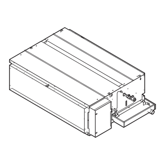
Page 11: Outlines And Dimensions
OUTLINES & DIMENSIONS 1. INDOOR UNIT PED-2EJA Service space:500 or more 10-ø3 (1.6, 2HP) PED-2.5EJA 12-ø3 (2.5HP) 50~150 Model Access door PED-2 1012 1070 1044 PED-2.5 Lifting bolt hole (14 22) Refrigerant piping flare connection (liquid ø9.52 copper tube):HP Refrigerant piping flare connection (gas ø15.88 copper tube):LP Drain R1(External thread) Electrical parts box Electric Heater···Only PEHD-EKHA Type... -
Page 12: Wiring Diagram
WIRING DIAGRAM MODELS:PED-2,2.5EJA WIRING DIAGRAM CN51 CN31 :OPTION PARTS MULTIPLE HEATER 4321 POWER X6 X5 CN30 CN120 OUTDOOR TO RC TRANSMISSION WIRES TRANS 12VDC 12CORE CONNECTOR CN4T CN21 CN20 CN50 FAN1 TRANS PIPE INTAKE DRAIN TO OUTDOOR UNIT 43 1 1 3 7 CONNECTING WIRES 12VDC(non-polar) -
Page 13: Indoor Unit 8. Disassembly Instructions
DISASSEMBLY INSTRUCTIONS Figure1. Disconnect the fan motor connecter (and the booster heater connector) Drain catches (Hidden) Heat exchanger Bottom plate Filter assembly Drain catches (Hidden) Bottom plate Drain pan 1 1 . Removing the fan motor 5. Remove the fan plate as follow: 1. - Page 14 Figure3. Fan base Sirocco fan Motor Housing assembly Bush Bush Piece Sirocco fan Piece Housing assembly...
- Page 15 Figure4. Pump cover Drain socket Drain pan cover assembly Drain pump assembly Drain hose Rubber plug Drain pan 2. Removing the drain water lift-up pump 1. Remove the drain pan. (Refer 1- 2.) 2. Disconnect the drain pump connector and drain sensor connector from the controller box.
-
Page 16: Parts List
PARTS LIST PED-2EJA PED-2.5EJA EXTERNAL PARTS 5, 6 3, 4 9, 10 7, 8 Qt’y/set Part No. Part Name Drawing No. PED- PED- Spec. 2EJA 2.5EJA S70 031 669 Bottom plate 1 W638939Z03 S70 011 669 Bottom plate 1 W638917Z03 S70 081 669 Bottom plate 2 ass’y W638940G02... - Page 17 PED-2EJA PED-2.5EJA BLOWER PARTS 2, 3 5, 6 9, 10 7, 8 5, 6 7, 8 Qt'y/set Part No. Part Name Drawing No. PED- PED- 2EJA 2.5EJA S07 652 131 Attachment W353715H01 S70 051 677 Fan base ass'y W638932G02 S70 061 677 Fan base ass'y W638905G02 S70 922 105...
- Page 18 PED-2EJA PED-2.5EJA CONTROL BOX PARTS Qt’y/set Part No. Part Name Drawing No. Spec. PED- PED- 2EJA 2.5EJA S70 918 717 Terminalbed P436109X01 <TB2> S70 979 717 Terminalbed P436110X01 <TB1> S70 010 310 Controller BG00L760G22 <I.B.> S70 11K 799 Transformer BG65T178H03 <T>...
-
Page 19: Electrical Parts
PED-2EJA PED-2.5EJA ELECTRICAL PARTS Qt’y/set Part No. Part Name Drawing No. Spec. PED- PED- 2EJA 2.5EJA S70 010 713 Remote controller BC00C006G34 J controller S70 A00 305 Remote controller cable BG00K507G02 S70 010 304 Cable ( for board ) BG78R190G10 0.5m... - Page 20 PED-2EJA PED-2.5EJA DRAIN WATER LIFT-UP PUMP PARTS (OPTIONAL PARTS) Qt’y/set Part No. Part Name Drawing No. Spec. PED- PED- 2EJA 2.5EJA S70 11K 355 Drain pump-94 BG56J144G13 S70 010 533 Cushion DB26F111H03 S70 K01 523 Drain socket ass’y BB00P145G17 S70 W28 266 Drain sensor ass’y DE00H343G21 S70 E69 558...
-
Page 21: Microprocessor Control
MICROPROCESSOR CONTROL... - Page 24 after...
-
Page 27: Trouble Shooting
TROUBLE SHOOTING... -
Page 29: Optional Parts
OPTIONAL PARTS 1. REFRIGERANT PIPES Part No. PAC-05FFS-E PAC-07FFS-E PAC-10FFS-E PAC-15FFS-E Pipe length Pipe size OD Liquid:/ø9.52 Gas:/ø15.88 Connection method Indoor unit:Flared Outdoor unit:Flared Note 1.How to connect refrigerant pipes. Factory supplied optional piping contains refrigerant at above atmospheric pressure. As long as the connection takes no more than 5 minutes, no air will enter, and there will be no need for air purging. - Page 30 3-3 HOW to connect program timer (1) Install the program timer next to the remote controller the same way as the remote controller is installed. (2) Connect the program timer and the remote controller with a 6-wire cable as shown in the figure below. NOTE: While the program timer is connected to the remote controller, the 24 hour ON/OFF timer on the remote controller will not operate.
- Page 31 4. CENTRALIZED REMOTE CONTROLLER Allows individual or combined control of up to 16 units. Part No. PAC-805RC 4-1 Dimensions 56.5 23.5 Unit:mm 4-2 Functions POWER ON / OFF switch Operation ON / OFF switch. "ENGAGED" indicator BACK AHEAD buttons When this indicator is lit, transmisson is in These buttons are used to designate the progress and all swiches are inoperative.
- Page 32 4-3 Connection method (1) Connection in the power supply cord. 1. Connect the power supply cord to the power supply terminal-block and fix in-place with a tie-wrap. Connect a single phase 200V AC(220, 230, 240V)to AN . As E is the GND terminal,be sure to ground the earth wire. 2.
-
Page 33: Parts Included
5. PROGRAM TIMER ADAPTER This adapter is needed when a program timer(PAC-815PT)or a centralised remote controller(PAC-805RC)is used. Part No. PAC-825AD 5-1 Parts included 1 ADAPTER ···································x1 2 3-core cable ·································· x1 2 3-core cable ·································· x1 Length:2m(6' 7") Length:2m(6' 7") 2 4-core cable ··································... - Page 34 6. TIMER ADAPTER This adapter is needed for system control and for operation via external contacts. Part No. PAC-SA89TA-E 7. REMOTE INDICATION ADAPTER This adapter is used for remote indication(operation/check.) Part No. PAC-559AD <Wiring> GREEN CN51 Power YELLOW supply ORANGE connector(5P) Electrical insulation is needed.
- Page 36 HEAD OFFICE MITSUBISHI DENKI BLDG. MARUNOUCHI TOKYO100 TELEX J24532 CABLE MELCO TOKYO MEE00K028 New publication, effective Nov. 2000 Issued in Nov. 2000 Specifications subject to change without notice. Printed in Japan...
Need help?
Do you have a question about the Mr. Slim PED-2EJA1.UK and is the answer not in the manual?
Questions and answers