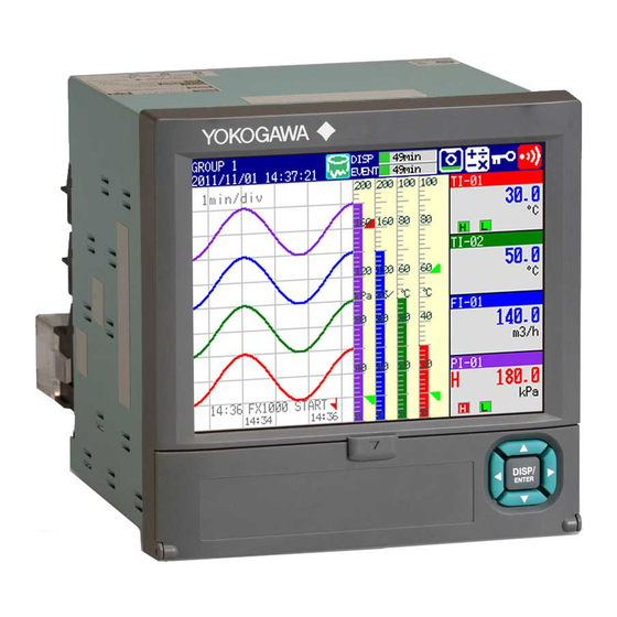
YOKOGAWA FX1002 User Manual
Paperless recorder
Hide thumbs
Also See for FX1002:
- Installation manual (4 pages) ,
- User manual (4 pages) ,
- First step manual (35 pages)

Related Manuals for YOKOGAWA FX1002


Summary of Contents for YOKOGAWA FX1002
- Page 1 User’s Manual Models FX1002/FX1004/FX1006/FX1008/ FX1010/FX1012 FX1000 First Step Guide IM 04L21B01-02EN 2nd Edition Y okogawa Electric Corporation...
-
Page 2: Table Of Contents
Contents Safety Precautions ..............................3 Handling Precautions of the FX ..........................4 Handling Precautions of the External Storage Medium (CF Card) ................4 Checking the Contents of the Package ........................5 Style number, release number, and firmware version number of the FX ..............6 Protection of Environment ............................7 Conventions Used in This Manual ..........................7 Introduction to Functions .............................8 Measured Items .................................8... - Page 3 Contents FX1000 User’s Manual (Electronic Manual: IM04L21B01-01EN) Chapter 1 Overview of Functions Chapter 2 Common Operations Chapter 3 Measurement Channels and Alarms Chapter 4 Switching Operation Screens Chapter 5 Operations for Changing the Displayed Contents Chapter 6 Saving and Loading Data Chapter 7 Customizing the Action Using the Event Action and Remote Control Functions (/R1 and /PM1 Options) Chapter 8 Using the Security Function Chapter 9 Computation and Report Functions (/M1, /PM1, and /PWR1 Options)
-
Page 4: Safety Precautions
• The company and product names used in this manual are not accompanied by the registered trademark or trademark symbols (® and ™). 2nd Edition: September 2012 (YK) All Rights Reserved, Copyright © 2011, Yokogawa Electric Corporation IM 04L21B01-02EN... -
Page 5: Handling Precautions Of The Fx
WARRANTY that is provided separately. • Use the Correct Power Supply • YOKOGAWA assumes no liability to any party for any loss Ensure that the source voltage matches the voltage of the power or damage, direct or indirect, caused by the user or any supply before turning ON the power. -
Page 6: Checking The Contents Of The Package
*2 /C2 and /C3 cannot be specified together. *3 /A3 or /A4A cannot be specified together with /F1. *4 /N2 cannot be specified for FX1002 or FX1004. *5 If /R1 is specified, /A4A, /TPS2, /TPS4, /PM1, or /PWR1 cannot be specified. -
Page 7: Style Number, Release Number, And Firmware Version Number Of The Fx
Standard Accessories Style number, release number, and firmware The standard accessories below are supplied with the instrument. version number of the FX Check that all contents are present and undamaged. Style number: This is the FX hardware number that is indicated on the name plate. -
Page 8: Protection Of Environment
Annex 1, this product is classified as a “Monitoring and Control instrumentation” product. Do not dispose in domestic household waste. To return unwanted products, contact your local Yokogawa Europe B. V. office. Conventions Used in This Manual • This manual covers information regarding FX1000 that have a suffix code for language “-2”... -
Page 9: Introduction To Functions
The fastest scan interval is 125 ms on the FX1002 and FX1004, and 125 ms on the FX1006, FX1008, FX1010, and FX1012. Up to four alarm conditions can be set for each measurement channel. -
Page 10: Fx System Configuration
Introduction to Functions FX System Configuration The FX can be used to configure a system as shown below. Referenced sections are of the FX1000 User’s Manual (IM 04L21B01-01EN.) Communication Interface User’s Manual (IM 04L21B01-17EN) Ethernet Temperature Recorder controller Serial communication* RS-232, RS-422A/485 Signal input Sec. -
Page 11: Names Of Parts
Names of Parts Front View Operation cover opened Operation cover opened Display various operation displays such as the trend display as well as setup displays. Display various operation displays such as the trend display as well as setup displays. USB port (/USB1 option) A USB port conforming to USB port... -
Page 12: Fx1000 Workflow
FX1000 Workflow When using the FX for the first time, carry out the following procedure. Install the FX. Installation FX1000 Safety Precautions and Installation Guide (IM 04L21B01-03EN) Chapter 12, in the FX1000 User's manual (IM 04L21B01-01EN) Connect input/output wires to the terminals and connectors on the Wiring rear panel, and connect the power cord. -
Page 13: Basic Operation
Basic Operation Panel Keys Key panel DISP/ENTER key and four arrow keys (up, down, left, and right) Switches the operation screen. Selects and enters setup items. Soft keys Selects the menu that is displayed at the bottom of the screen. DISP/ENTER key Up arrow key Right arrow key... -
Page 14: Display On The Status Display Section
Displays the progress using a green bar graph. The frame indicates the file save interval (display data) or the data length (event data). in progress Error in internal memory. Contact your nearest YOKOGAWA dealer for repairs. Memory sampling icon Displays the remaining memory sampling time for the left bar graph. Alarm icon Displayed when any alarm is activated. -
Page 15: Run Modes
Basic Operation Run Modes Mode Transition Diagram Power on Operation mode Setting mode Basic setting mode End menu > DISP/ENTER ESC > DISP/ENTER MENU key Hold down FUNC Basic setting Operation display Setting menu display for 3 s menu display MENU key ESC key MENU key... -
Page 16: Entering Values And Characters
Basic Operation Entering Values and Characters The character/number input window and DISP/ENTER key are used to set the date/time, set the display span of the input range, set the tag, set the message string, enter the password, etc. Character/number input window DISP/ENTER key and four arrow keys (up, down, left, and right) Cursor... -
Page 17: Inserting/Removing A Cf Card
Basic Operation Inserting/Removing a CF Card The following procedure is for FXs that have a CF card slot (suffix code -4.) Inserting a CF Card Open the front cover. CAUTION Forcing the CF card into the slot with the upside down may cause damage. CF card With the label “This side up”... - Page 18 Basic Operation Press the CF card eject button. When you eject the CF card, the CF card icon disappears. Press the eject button in until it clicks. The eject button stops at depressed position. Pinch the left and right sides of the CF card and remove it.
-
Page 19: Setting The Functions And Operations
Setting the Functions and Operations The contents of the screens used in the explanations in the following operation example may vary depending on the installed options and the FX settings. Setting the Date/Time In this example, we will change the date from the 1st to the 6th. After carrying out this step, reset the time to the correct date/time. -
Page 20: Setting The Input Range
Setting the Functions and Operations Setting the Input Range Configure the FX so that it measures temperature on measurement channel 1 and flow rate on measurement channel 2. Setting the Temperature Measurement Channel, the Input Range, and the Tag Type T Channel 1 thermocouple 0.0 to 200.0°C... - Page 21 Setting the Functions and Operations Press DISP/ENTER once. Select First-CH. 001 is displayed next to First-CH, so do not change this setting. Press the +1 soft key once to set First-CH and Last-CH to 002. Press the down arrow key once to move the cursor to Mode. Press the TC soft key once.
- Page 22 Setting the Functions and Operations Press DISP/ENTER once. The changed items are entered, and the cursor returns to First-CH. The changed items change from yellow to white. Press ESC three times or MENU twice to return to the operation mode screen. Operation complete.
-
Page 23: Setting The Flow Rate Measurement Channel, The Input Range, The Alarm, And Tag
Setting the Functions and Operations Setting the Flow Rate Measurement Channel, the Input Range, the Alarm, and Tag Flowmeter Channel 2 4 - 20 mA Convert to 1-5 V with a shunt resistor Setup Item Description Number in the Figure Channel Use channel 2. -
Page 24: Assigning Channels To Groups
Setting the Functions and Operations Assigning Channels to Groups In this example, we will assign channels 1 and 2 to group 1. Group 1 Channel 1 Channel 2 Setup Item Description Number in the Figure Group Assign channel 1 and 2 to group 1. (1) Group Press MENU (to switch to setting mode) >... -
Page 25: Setting The Time Scale
Setting the Functions and Operations Setting the Time Scale Set the time per division of the trend waveform to 2 minutes. The sampling interval (the time corresponding to 1 dot) is 4 s when the trend interval is 2 min. 30 dots ×... -
Page 26: Saving The Setup Data
Setting the Functions and Operations Saving the Setup Data The following procedure is for FXs that have a CF card slot (suffix code -4.) In this example, we will save the setup data to a file named “SF2” on the CF card. Display the operation mode screen. -
Page 27: Starting Memory Sampling
Setting the Functions and Operations Starting Memory Sampling Press START once. Memory sampling progress DISP: Display data Recording data EVENT: Event data START key Operation complete. Stopping Memory Sampling Press STOP once. Display the confirmation window. Select Mem+Math or Memory using the left and right arrow keys. Memory Stops memory sampling. -
Page 28: Switching The Trend Display, Digital Display, And Bar Graph Display
Setting the Functions and Operations Switching the Trend Display, Digital Display, and Bar Graph Display Press DISP/ENTER once to show the display selection menu. Left arrow key Up arrow key Right arrow key DISP/ENTER key Down arrow key Press the down arrow key to select TREND, DIGITAL, or BAR. Press the right arrow key once to display the sub menu. -
Page 29: Writing The Message "Start
Setting the Functions and Operations Writing the Message “START” Registering the Word “START” in Message Number 1 Press MENU (to switch to setting mode) > select the Menu tab > Message > DISP/ENTER Press the 1-10 soft key. The message, “Message numbers 1-10 can also be used for free message” appears. Press DISP/ENTER. - Page 30 Setting the Functions and Operations Writing Message Number 1 “START” This operation can only be carried out while memory sampling is in progress. The message is displayed on the trend display. Show the trend display first. Press FUNC (display the FUNC key menu), press the Message soft key, and press the 1-10 soft key.
-
Page 31: Monitoring The Fx On A Pc Browser (Ethernet) (/C7 Option)
Monitoring the FX on a PC Browser (Ethernet) (/C7 Option) In this example, we will connect the PC and the FX via hub in a one-to-one relationship and display and monitor the FX screen on a browser on the PC. Ethernet Setup Item Description... - Page 32 Monitoring the FX on a PC Browser (Ethernet) (Option /C7) (2) Enabling the Web Server Function on the FX Select the Menu tab > Communication (Ethernet) > Server > Server modes. (3) Display the FX Screen on the PC Select the Menu tab > Communication (Ethernet) > Web page. (4) Save the Settings Press ESC twice to return to the basic setting menu.
-
Page 33: Commands
Monitoring the FX on a PC Browser (Ethernet) (Option /C7) (6) Checking the Connection Send the command below from the PC and check that a correct response is returned. Send >ping 192.168.1.101 Response example >Reply from 192.168.1.101: bytes=32 time<10ms TTL=255 (7) Displaying the FX Screen on the Browser Start the browser on the PC. -
Page 34: Displaying The Measured Data On Daqstandard
Displaying the Measured Data on DAQSTANDARD In this example, we will display the measured data using the accompanying software program, DAQSTANDARD. Insert the CF card containing the measured data file into the PC that has DAQSTANDARD installed. Start DAQSTANDARD Viewer. From the File menu, choose Open.
Need help?
Do you have a question about the FX1002 and is the answer not in the manual?
Questions and answers
My paperless recorder Yokogawa FX1012 appears "E201 Not enough free space on media" . How to solve it and what should i do to ensure it does not appear again?
To resolve the "E201 Not enough free space on media" error on the YOKOGAWA FX1012 paperless recorder, follow these steps:
1. Check Available Space – Verify the free space on the external storage medium (CF card).
2. Delete Unnecessary Data – Remove old or unnecessary files to free up space.
3. Format the Storage Medium – If necessary, back up important data and format the CF card using the recorder’s formatting function.
4. Use a Compatible Storage Medium – Ensure the CF card is compatible with the FX1012 and in good condition.
5. Avoid Writing Failures – Operate within the recommended temperature range (above 10°C after warm-up and below 40°C).
6. Proper Handling – Insert the storage medium only when saving data and remove it when not in use. Avoid touching the CF card when static electricity is present.
7. Regular Maintenance – Periodically check space availability and organize stored data to prevent future occurrences.
Following these steps will help resolve and prevent the error.
This answer is automatically generated