Table of Contents
Advertisement
Quick Links
ASSEMBLY INSTRUCTIONS
PRE-ASSEMBLY
Before you begin: These instructions will guide you in properly assembling the unit. Please review all the steps before beginning assembly.
Carefully adhere to the Assembly Instructions and User Instructions to help ensure user safety and product integrity.
1. It is your responsibility to familiarize yourself with the proper use of the equipment and the inherent risks of inversion, such as falling on your head
or neck, pinching, entrapment or equipment failure.
2. This product is not designed for persons over 250 lbs (113.6 kg) Structural failure could occur or head/neck may impact floor during inversion.
Serious injury or death could result.
3. DO NOT use with the EZ-Up Inversion Rack in doorways wider than 36" (91 cm).
4. ONLY use in solid wood doorways built according to national building codes. DO NOT use in faux or metal doorways.
5. You must use the screws provided. DO NOT substitute with other length screws.
6. DO NOT use the equipment without a licensed physician's approval and a review of the medical containdications, as noted in the Owner's Manual.
7. Failure to assemble and/or use the equipment as directed may void the manufacturer's warranty on this product and could result in injury or death.
8. DO NOT use the EZ-Up Inversion Rack until you have thoroughly and carefully read the Owner's Manual, viewed the Instructional Video, reviewed
product labeling and all other accompanying documents, and inspected the equipment.
9. The steps in the video directly coincide with the steps detailed in these Assembly Instructions.
10. Make sure that all fasteners are secure.
11. Follow each step in sequence. Do not skip ahead.
12. ONLY one person at a time should use the EZ-Up
13. Prior to use, test and inspect the EZ-Up Inversion Rack to ensure secure installation.
14. Replace defective parts immediately and/or keep the equipment out of use until repair.
Carefully remove the individual parts from the carton. You should have all of the items
listed below. If any items are missing or damaged, contact your retailer or customer
service directly (See Pg. 2 of the Owner's Manual).
E1-1040
E1-1047
E1-1059
ASSEMBLY
Figure 1
(larger diameter
tubes)
2
1
3
Figure 2
Figure 2A
2
countersink
1 ¾"
1
3
2"
Figure 3
4
(smaller diameter
tubes)
5
!
TM
Inversion Rack.
E1-1050
E1-1052
E1-1043
H1-1904
H1-1905
H1-3011
STEP 1.
Assemble the three larger diameter tubes (E1-1040, E1-1043, E1-1052)
which are marked by a 1, 2 and 3 at each joint:
• Separate the three larger diameter tubes from the three smaller diameter tubes.
The larger diameter tubes use joint numbers 1, 2, and 3.
• Lay out the three larger tubes in relationship to each other. See Figure 1. Be
sure that the parts are assembled so that 1 mates to 1, 2 mates to 2, and 3
mates to 3.
• Loosely assemble joints 1 and joints 3 using the 2" (5 cm) bolts (H1-1905). See
Figure 2. DO NOT TIGHTEN THE BOLTS YET.
• Loosely assemble joint 2 with the 1¾" (4.4 cm) bolt (H1-1904) and lock nut (H1-
3011). Insert the bolt so that its head fits in the countersink. See Figure 2A.
STEP 2.
Assemble the three smaller diameter tubes (E1-1047, E1-1050, E1-1054)
which are marked by a 4, 5 and 6 at each joint:
2"
• Lay out the three smaller diameter tubes in relationship to each other . See
Figure 3. Be sure that the parts are assembled so that 4 mates to 4, 5 mates to
5, and 6 mates to 6.
• Loosely assemble joints 5 and joints 6 using the 2" (5 cm) bolts (H1-1905). DO
6
NOT TIGHTEN THE BOLTS YET.
• Loosely assemble joint 4 with the 1½" (3.8 cm) bolt (H1-1904) and lock nut
(H1-3011). Insert the bolt so that its head fits in the countersink. See Figure 2A.
DO NOT DISCARD - KEEP FOR FUTURE REFERENCE.
WARNING
Items for Assembly:
Large diameter 'L' Bar
Small diameter 'L' Bar
E1-1054
Small Straight Bar w/ Warning Label
Large Straight Bar w/ Blue Foam
Large diameter 'Elbow' Bar
Small diameter 'Elbow' Bar
Two (2) Locking Brackets
Four (4) 2" (5 cm) Bolts
Two (2) Bolts: 1 - 1¾" (4.4 cm); 1 - 1½" (3.8 cm)
Six (6) 2" (5 cm) Wood Screws
Not included: Medium Phillips Head screwdriver,
H1-5005
Adjustable Wrench, Drill motor w/ 5/32" drill bit.
w/ Lock Nuts
Item #
E1-1040
E1-1047
E1-1050
E1-1043
E1-1052
E1-1054
E1-1059
H1-1905
H1-1904
H1-3011
H1-5005
Advertisement
Table of Contents

Related Manuals for Hang ups Teeter EZ-Up Inversion Racck


Summary of Contents for Hang ups Teeter EZ-Up Inversion Racck
- Page 1 ASSEMBLY INSTRUCTIONS PRE-ASSEMBLY Before you begin: These instructions will guide you in properly assembling the unit. Please review all the steps before beginning assembly. Carefully adhere to the Assembly Instructions and User Instructions to help ensure user safety and product integrity. WARNING 1.
- Page 2 ASSEMBLY Figure 4 STEP 3. Final Assembly: • Slide the smaller half into the larger half. See Figure 4. Tighten all bolts using a screwdriver and wrench. The width of the EZ-Up Inversion Rack may be adjusted to fit doorways 28 to 36” (71 to 91 cm) wide by sliding the smaller half in or out, depending upon the size of your door frame.
- Page 3 OWNER’S MANUAL Weight Capacity: Max 250 lbs. / 113.6 kg WARNING Important Safety Instructions: It is your responsibility to familiarize yourself with the proper use of the equipment and the inherent risks of inversion, such as falling on your head or neck, pinching, entrapment or equipment failure.
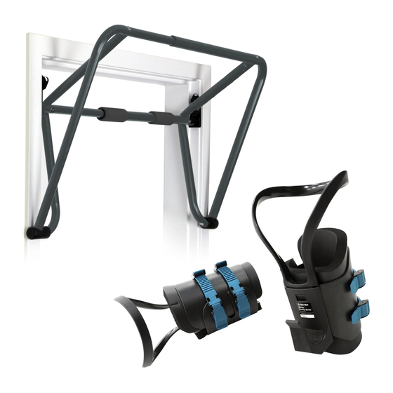
- Page 4 OWNER’S MANUAL HELPFUL SUGGESTIONS FOR INVERTING EZ-Up INVERSION RACK AND GRAVITY BOOTS 1. Begin Slowly: • At full 90º inversion, begin with only 1-2 minutes per session. • Stay inverted only as long as you are comfortable, even if only for a few seconds at first. •...
Need help?
Do you have a question about the EZ-Up Inversion Racck and is the answer not in the manual?
Questions and answers