Table of Contents
Advertisement
Quick Links
Total solder points: 150
Skill level :
Beginner 1o 2o 3þ 4o 5o Advanced
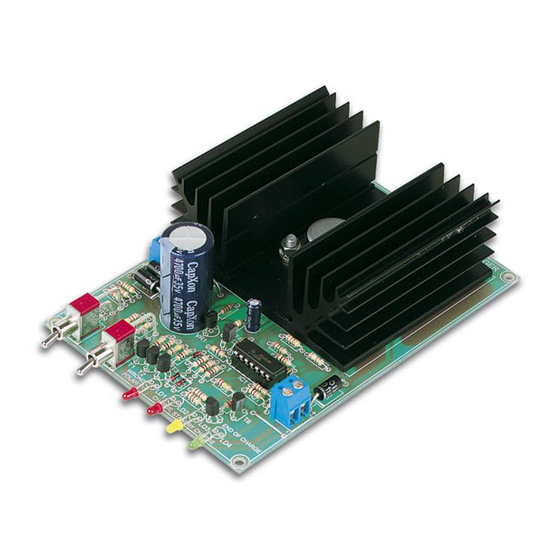
INTELLIGENT LEAD ACID BATTERY CHARGER
Features:
þ
Suitable for 6V and 12V sealed and open lead-acid batteries
þ
Fully automatic charge and maintenance cycle
þ
Status indicators for charge, float and end-of-charge
þ
Protected against polarity reversal
þ
Simply connect and forget
Specifications :
þ
Charge current : 0.3 or 1A selectable
þ
Power supply : 2x9V/25VA (our type 2090250MST)
þ
Dimensions (wxdxh): 97 x 140 x40mm / 3.8"x 5.5"x1.6"
þ
Not suitable for non-rechargeable or NiCd/NiMH batteries
modifications reserved
Options :
þ
Transformer prim. 230V - sec. 2x9V/25VA: 2090250MST
þ
Enclosure: TKAUS22G
þ
Power cord: NETSNOER
ILLUSTRATED MANUAL
K8012
H8012P-ED1
Advertisement
Table of Contents

Related Manuals for Velleman K8012


Summary of Contents for Velleman K8012
-
Page 1: Specifications
Total solder points: 150 Skill level : Beginner 1o 2o 3þ 4o 5o Advanced INTELLIGENT LEAD ACID BATTERY CHARGER K8012 Features: þ Suitable for 6V and 12V sealed and open lead-acid batteries þ Fully automatic charge and maintenance cycle þ... - Page 2 COLOR= 2… 5 4K7= ( 4 - 7 - 2 - B ) 4K7= ( 4 - 7 - 0 - 1 - 1 ) COLOUR CODIFI- KLEUR CODICE CODIGO CODIGO VÄRI FÄRG FARVE FARGE FARB CODE CATION KODE SCHEMA DE COL- COLORE KOODI...
- Page 3 __________________________________________________________________________________________________________________________________________________________ 1. Assembly (Skipping this can lead to troubles ! ) Ok, so we have your attention. These hints will help you to make this project suc- cessful. Read them carefully. 1.1 Make sure you have the right tools: • A good quality soldering iron (25- 40W) with a small tip.
- Page 4 _______________________________________________________________________________________________________________________________________________________ 1.3 Soldering Hints : Mount component Make sure the solder Trim excess leads as against the PCB surface joints are cone-shaped close as possible to the and carefully solder the and shiny solder joint leads...
-
Page 5: Jumper Wires
__________________________________________________________________________________________________________________________________________________________ q R2: 27K (2 - 7 - 0 - 2 - 1) AXIAL COMPONENTS ARE q R3: 120K (1 - 2 - 0 - 3 - 1) TAPED IN THE CORRECT q R4: 180K (1 - 8 - 0 - 3 - 1) MOUNTING SEQUENCE ! q R5: 10K (1 - 0 - 3 - B) START... -
Page 6: Voltage Reference
_______________________________________________________________________________________________________________________________________________________ 6. TRANSISTORS 4. DIODES (Watch the polarity!) D... CATHODE q D1: 1N4148 q D2: 1N4148 q T1: BC547 q D3: 1N4148 q T2: BC547 q D4: 1N5400 …1N5408 q T3: BC547 q D5: 1N5400 …1N5408 q T4: BC547 q D6: 1N5400 …1N5408 q T5: BC547 q D7: 1N5400 …1N5408 q T6: BC557... -
Page 7: Power Transistor
__________________________________________________________________________________________________________________________________________________________ 9. SWITCHES 12. LEDS (Watch the polarity!) SW... COLOUR=2...5 q SW1: SINGLE POLE (ON-ON) q SW2: SINGLE POLE (ON-ON) CATHODE 10. ELECTROLYTIC CAPACI- CATHODE LD... TORS (Watch the polarity!) C... q LD1: 3mm LED RED (2) q LD2: 3mm LED RED (2) q LD3: 3mm LED YELLOW (4) q C1: 2µ2 q LD4: 3mm LED GREEN (5) - Page 8 Perform all tests as shown below, before the first use of the unit. It allows you to check every function of your charger kit. Use the supplied 5W dummy load resistors and a reliable multi-meter. 13.6V= K8012 ACCU AC POWER Put SW2 in the 12V position. Measure the voltage across the output termi- nals.
- Page 9 __________________________________________________________________________________________________________________________________________________________ Put SW2 in the 6V position. Measure the voltage across the output termi- nals. Output voltage should be 6.8V +/- 0.2V 14.7V= K8012 AC POWER ACCU >4Ah Put SW2 in the 12V position, put SW1 in the >4Ah position. Connect the supplied 33Ω/5W resistor to the output terminals.
- Page 10 _______________________________________________________________________________________________________________________________________________________ 0.3A= K8012 Ω AC POWER ACCU <4Ah 12V Put SW2 in the 12V position, put SW1 in the <4Ah position. Connect the supplied 8.2Ω resistor in series with the multi-meter. Switch the multi-meter to the ‘10A DC’ -position. It should read 0.3A +/- 0.03A.
-
Page 11: Connection Diagram
If the unit never leaves the ‘charge’ cycle, this could point to either a defec- tive battery, a too low charge current setting, or a battery with a too large capacity. 15. CONNECTION DIAGRAM K8012 ON/OFF Fuse R1823A/B 0.25A Slow... - Page 12 _______________________________________________________________________________________________________________________________________________________ 16. ASSEMBLING...
-
Page 13: Rear Panel
__________________________________________________________________________________________________________________________________________________________ 17. DRILL PATTERN ENCLOSURE ‘TKAUS22G’ 24,5 BOTTOM REAR PANEL 36,5 27,5 24,5 FRONT PANEL 17,5 17,5 25,5 All distances are expressed in mm... -
Page 14: Pcb Layout
_______________________________________________________________________________________________________________________________________________________ 18. PCB LAYOUT VELLEMAN P8012'1 LEAD ACID BATTERY CHARGER BATTERY CAPACITY SELECT VOLTAGE SELECT END OF CHARGE </>4Ah T1 T2 WRONG FLOAT POLARITY CHARGE CHARGE... - Page 15 __________________________________________________________________________________________________________________________________________________________ 19. DIAGRAM...
Need help?
Do you have a question about the K8012 and is the answer not in the manual?
Questions and answers