Table of Contents
Advertisement
Quick Links
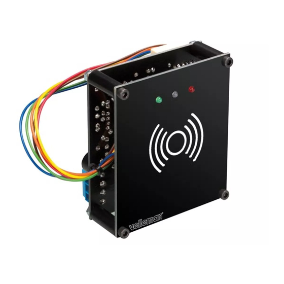
K8019
K8019
ILLUSTRA
ILLU
ILLUSTRATED ASSEMBLY MANUAL H8019IP'1
L
LLU
LLU
LLU
STRA
STRA
RA
RATED
T
TED
TED
TED
TED
D
D
ASS
AS
AS
ASSE
ASSE
AS
ASSE
ASS
EMBLY
MBLY
MBLY
M
BLY
BLY
LY
Y
Y
PROXIMITY CARD
PROXIMITY CARD
READER WITH USB
READER WITH USB
INTERFACE
INTERFACE
M
MANUAL
MAN
M A
M
UAL
UAL
AL
AL
H80
H801
H801
H801
1
1
9 IP
9 IP'
9
9
9IP'
9IP'
9IP
9IP'
P
1
1
1
Features
• Store up to 250 tags.
• With USB interface for confi g-management.
• Free tag management application for PC.
• Fully documented protocol, write your own application.
• Tags can also be entered using a 'mastercard'.
• Toggle or pulse NO/NC relay output.
• Adjustable pulse time: 1s to 4 min. approx.
• 3 status leds and buzzer.
• Two tags supplied (card-type).
• Works standalone.
Specifi cations
• EM4100 compatible.
• Relay contact: 3A/24VDC.
• Power supply: 12VDC or 5VDC (USB)*
• Power consumption: 100mA max.
• Dimensions: 69x80x47mm / 2.71x3.15x1.85"
Optional:
◊ Acces card : HAA2866/TAG
◊ Access badge : HAA2866/TAG2
*Only for confguration and tag learning. Relay will not operate.
Advertisement
Table of Contents

Related Manuals for Velleman K8019


Summary of Contents for Velleman K8019
- Page 1 K8019 K8019 ILLUSTRATED ASSEMBLY MANUAL H8019IP’1 ILLU ILLUSTRA STRA STRA RATED ASSE ASSE ASSE EMBLY MBLY MBLY MANUAL H801 H801 H801 9IP’ 9IP’ 9IP’ 9 IP’ 9 IP PROXIMITY CARD PROXIMITY CARD READER WITH USB READER WITH USB INTERFACE INTERFACE Features Specifi...
- Page 2 Subscribing our newsletter?, visit www.vellemanprojects.eu Forum Forum Participate our Velleman Projects Forum...
- Page 3 Velleman N.V. Legen Heirweg 33 9890 Gavere (België)
- Page 4 assembly 1. Assembly (Skipping this can lead to troubles ! ) hints Ok, so we have your attention. These hints will help you to make this project successful. Read them carefully. 1.1 Make sure you have the right tools: • A good quality soldering iron (25-40W) with a small tip. •...
- Page 5 DO NOT BLINDLY FOLLOW THE ORDER OF THE COMPONENTS ONTO THE TAPE. ALWAYS CHECK THEIR VALUE ON THE PARTS LIST! - 5 -...
- Page 6 Construction CONSTRUCTION Ceramic Capacitors Resistors C7 : 100nF (104) R... C8 : 100nF (104) Component PCB C9 : 100nF (104) C10 : 100nF (104) C11 : 100nF (104) Jumper wire C20 : 100nF (104) ...
- Page 7 Construction Ceramic Capacitors Buzzer Electrolytic capacitors C1: 10nF (103) C2: 10nF (103) Watch the polarity! Watch the polarity! Watch the polarity! Watch the polarity! C3: 10nF (103) C... C4: 4.7nF (472) C5: 4.7nF (472) C15: 4,7μF ...
- Page 8 Construction Voltage regulator RFID reader PCB Led’s. Watch the polarity! VR1: UA7805 Relay Bend the leads LD1 Bend the leads (red) LD2 (blue) LD3 (green) RY1: VR15121C IC’s Watch the position Watch the position of the notch! of the notch! ...
- Page 9 Construction Board to wire (Female) Connect to main board - 9 -...
- Page 10 Assembly ASSEMBLY Spacer M3 x 25mm Allen screw M3 nut M3 nut - 10 -...
- Page 11 Hook-up example HOOK-UP EXAMPLE - 11 -...
-
Page 12: Software Installation
Software installation IV. SOFTWARE INSTALLATION Step 4: Select the destination on your PC. Step 2: open the fi le en select the software. Remark: Software installation is not mandatory, since the fi rst card that is learned puts the unit into learnmode. Once in learnmode, you can learn more cards. -
Page 13: Driver Installation
V. DRIVER INSTALLATION Connect the USB connector of the K8019 to your PC using an USB cable. With the fi rst connection, you should install the USB driver onto the PC fi rst. You can download the manual for installing the driver on our website. - Page 14 Indications VI. INDICATIONS A. Leds LD3 LD2 LD1 The card reader has three colored leds: green, blue and red. STATUS Relay off power on Blinking learning mode enabled Relay energized B. Sound Valid card / card stored invalid card (learning mode) enter / leave learn mode - 14 -...
-
Page 15: Learning Mode
Learning mode VII. SET-UP Relay When a valid card is presented the relay is energized. The relay has three confi gurations (the confi guration is done via the PC): • Toggle: swipe= ON, swipe= OFF. • Momentary: ON while card is present. •... - Page 16 VIII. HOW DOES AN RFID WORK? An RFID tag sleeps in normal mode: it does not perform any activities and does not use any power. This will change as soon as the tag moves through the reader’s fi eld. An RFID reader emits radio CHIP with EPC code.
-
Page 17: Schematic Diagram
Schematic diagram 1N4148 1N4148 220K CON BTWM6 1N4148 100p 100n IC1A IC1B LM358 100K LM358 220K 100n R5 100K DATA 100n 100p BC547 4μ7 BC557 470p 100n 1N4148 USB CON CC089 ICSP CONNECTOR VBUS RA1/D-/PGC USB_D- RA3/MCLR/VPP RA0/D+/PGD USB_D+ VUSB 470n RB4/AN10/SDI/SDA RC0/AN4/C12IN+/INT0/VREF+... - Page 18 - 18 -...
-
Page 19: Open Collector Outputs
Leds and how to use them Leds feature a specifi c voltage Never connect leds in parallel drop, depending on type and colour. Check the datasheet for exact voltage drop and rated current ! How to Calculate the series resistor: Example: operate a red led (1.7V) on a 9Vdc source. - Page 20 The new Velleman Projects catalogue is now available. Download your copy here: www.vellemanprojects.eu Modifi cations and typographical errors reserved - © Velleman nv. H8019IP’1 (rev.1) Velleman NV, Legen Heirweg 33 - 9890 Gavere.
Need help?
Do you have a question about the K8019 and is the answer not in the manual?
Questions and answers