Table of Contents
Advertisement
Quick Links
Advertisement
Table of Contents

Related Manuals for Velleman K7302


Summary of Contents for Velleman K7302
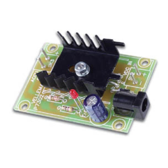
- Page 1 UNIVERSAL BATTERY CHARGER K7302 ILLUSTRATED ASSEMBLY MANUAL H7302IP-1...
-
Page 2: Specifications
Features & Specifications Specifications: Charges Ni Cd or Ni MH batteries. Ideal for in car use. Transforms a mains adapter into a charger (adapter socket included). Charge cellular phone, toys, portables, video batteries … Selectable charge current. ... -
Page 3: Assembly Hints
Assembly hints 1. Assembly (Skipping this can lead to troubles ! ) Ok, so we have your attention. These hints will help you to make this project successful. Read them carefully. 1.1 Make sure you have the right tools: A good quality soldering iron (25-40W) with a small tip. ... - Page 4 REMOVE THEM FROM THE TAPE ONE AT A TIME ! DO NOT BLINDLY FOLLOW THE ORDER OF THE COMPONENTS ONTO THE TAPE. ALWAYS CHECK THEIR VALUE ON THE PARTS LIST!
-
Page 5: Charging Batteries
Charging batteries Charging batteries Determining the charge current: Before building the kit, one must determinate how much current will be used to charge the battery or bat- tery pack. It is advisable to charge the battery with a current that is 10 times smaller then the battery capacity, and to charge it for about 15 hours. - Page 6 Charging batteries Determining the supply voltage : This table indicates the minimum and maximum voltages to supply the charger. Example: To charge a 6V battery a minimum supply voltage of 12V is needed, the maximum voltage is then 15V. Supply voltage Usable adapter Battery Voltage Min.
- Page 7 Construction 1. Diode. Watch the polarity ! 3. Resistor 4. LED (check the polarity!) D1 : 1N4007 R... D... CATHODE 10mm 17mm LD... CATHODE The value of resistor R2 deter- LD1 : 3mm low current RED Resistor mines the charge current: 1/2W ...
- Page 8 Construction 6. Electrolytic Capacitor. 8. Transistor 9. Mounting in an housing Watch the polarity ! The PCB can easily be mounted M3 NUT C1 : 220µF into our housing type G403. M3 LOCK WASHER M3 WASHER Due to heat dissipation, it is ad- visable to make some 4mm venti- C...
- Page 9 Connection 10. Connection P7302 DC ADAPTOR RECHARGEABLE BATTERY ACCU P7302 RECHARGEABLE BATTERY DC POWER SUPPLY ACCU P7302 RECHARGEABLE BATTERY CIGARETTE LIGHTERPLUG ACCU Connecting the supply voltage and the battery. See table on page 6 for suitable supply voltage...
-
Page 10: Schematic Diagram
Schematic diagram 11. Schematic diagram +OUT 6.5...21VDC 1.2...12V ACCU 120/0...5W -OUT CHARGE CURRENT DJ-005 BD135 220µF/25V 50mA 47/0.25W 100mA 18/0.25W 200mA 6.8/0.25W 300mA 3.9/0.5W 400mA 2.7/0.5W L-934LSRD RED... - Page 11 12. PCB ACCU VELLEMAN P7302 VDC IN...
- Page 12 VELLEMAN NV Legen Heirweg 33, B-9890 GAVERE Belgium (Europe) Modifications and typographical errors reserved - © Velleman nv. H7302IP’2 - 2014 (rev.1) 5 4 1 0 3 2 9 2 9 0 3 6 8...
Need help?
Do you have a question about the K7302 and is the answer not in the manual?
Questions and answers