Advertisement
Table of Contents
- 1 Installation Guide
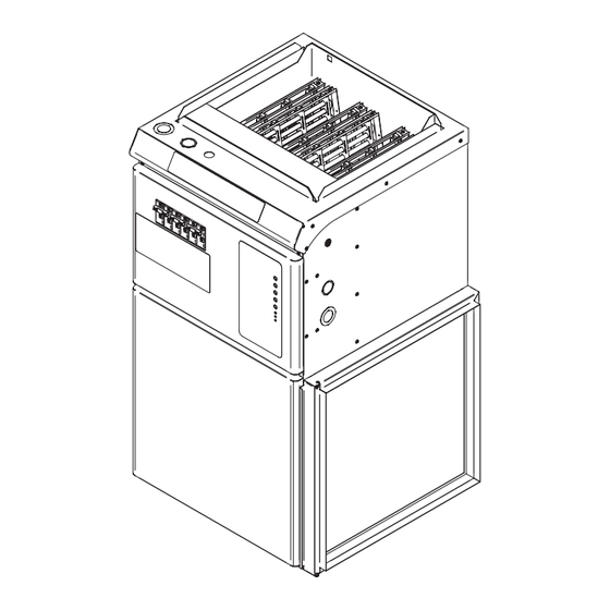
- 2 Technical Drawings
- 3 Specifications
- 4 Installation
- 5 Ducts and Filters
- 6 Optional Accessories
- 7 Control Panel
- 8 Operation
- 9 Air Conditioning
- 10 Heat Pump
- 11 Airflow Settings
- 12 Air Filter
- 13 Preventive Maintenance
- 14 Troubleshooting
- 15 Limited Warranty
- Download this manual
See also:
User Manual
installation guide
sefeCM series
electric furnace
This section must be read carefully by the installer.
The installer must also read the user's guide since it contains other important information.
For further information or to consult this guide online, please visit our website at www.stelpro.com
replacement component list included
this unit
complies with
csa and ul
standards
This unit is approved according
to the Canadian and American
manufacturing standards.
INSSEFECMI0513
Advertisement
Table of Contents

Related Manuals for Stelpro SEFECM SERIES


Summary of Contents for Stelpro SEFECM SERIES
-
Page 1: Installation Guide
This section must be read carefully by the installer. The installer must also read the user’s guide since it contains other important information. For further information or to consult this guide online, please visit our website at www.stelpro.com INSSEFECMI0513... -
Page 2: Technical Drawings
warning Before installing and operating this product, the user and/or installer must read, understand and follow these instructions and keep them handy for future reference. If these instructions are not followed, the warranty will be considered null and void and the manufacturer deems no further responsibility for this product. -
Page 3: Specifications
specifications elecTRic fuRNace Type volTs leNgTh (iN.) WidTh (iN.) depTh (iN.) sefecm1021B 240/208 10/7.5 44/38 1/2 ECM 36 9/16 20 1/8 21 3/16 sefecm1521B 240/208 15/11.2 65/56 1/2 ECM 36 9/16 20 1/8 21 3/16 sefecm1821B 240/208 18/13.5 78/67 1/2 ECM 36 9/16 20 1/8 21 3/16... -
Page 4: Ducts And Filters
DuCTs AnD fiLTers Ducts must be designed to deliver the correct airflow at the specified external static pressure . You should insulate the ducts crossing non-heated areas. Moreover, use flexible return and supply connectors in order to avoid vibrations as much as possible. To make your furnace even quieter, follow these instructions: 1. - Page 5 electrical connections of the furnace Note that this product must be connected by a qualified electrician according to the electrical and building codes effective in your region. for 240 vac connection, you can use copper or aluminum wire (75°c (165°f)), except for 27 kw and 30 kw models where only copper wire is allowed.
- Page 6 electrical connection of the thermostat The thermostat must be mounted to a FuRNACE TO 24 V THERMOSTAT CONNECTIONS WITH HEAT PuMP connection box, at around 1.5 m (5 feet) above the floor level, on a section of the wall * R terminal : 1A maximum exempt from pipes or air ducts.
-
Page 7: Control Panel
ConTroL PAneL LÉgenD 1. Low sPeeD ConTinuous VenTiLATion button: provides the 7. 5 kw ConTinuous heATing button: provides the selection of selection of the low speed continuous ventilation mode. the 5 kW continuous heating mode. 2. Low sPeeD ConTinuous VenTiLATion pilot light: indicates 8. -
Page 8: Air Conditioning
The SEFECM series allows to adjust the continuous ventilation airflows independently from the ventilation airflow in heating mode. Note that it also allows airflows as low as 300 cfm in continuous ventilation. This reduces ventilation noises considerably. -
Page 9: Airflow Settings
airflow settings The SEFECM furnace is equipped with an efficient ECM motor A potentiometer allowing to adjust the airflow corresponds to each of that can maintain constant airflow regardless of the static pressure these five modes. The potentiometers are located in front of the furnace variation in the ducts. -
Page 10: Air Filter
anticipator If you install a thermostat equipped with a heat anticipator, refer to the user’s guide of the thermostat to adjust it. Using an ampmeter, measure the current on the single stage thermostat. ProCeDures To foLLow 1. Set the anticipator to its highest setting (ineffective); 2. -
Page 11: Troubleshooting
ConTroL CArD AuToDiAgnosTiC DIAGNOSTIC ledS LOCATION ON CONTROL CARD The control card of the furnace is equipped with three LED pilot lights that allow easy and quick diagnostic of its essential functions. They are located at the bottom left of the control card (see illustration). HEARTBEAT LED PILOT LIGHT The first LED pilot light from the top is blinking in normal operation;... - Page 12 replacement component list Ref. # paRT # descRipTioN ELF-SEF0521 ELEMENT ASSEMBLY 5 KW ELF-SEF0421 ELEMENT ASSEMBLY 4 KW ELF-SEF0221 ELEMENT ASSEMBLY 2 x 2.5 KW BLO-004 SQuIRREL CAGE & BLOWER 10-8 BLO-005 SQuIRREL CAGE & BLOWER 12-11 MO-034 MOTOR, ECM 1/2 HP MO-035 MOTOR, ECM 1 HP SUP-004...
-
Page 13: Limited Warranty
Stelpro reserves the right to examine or to ask one of its representatives to examine the product itself or any part of it before honoring the warranty. Stelpro reserves the right to replace the entire unit, refund its purchase price or repair a defective part.
Need help?
Do you have a question about the SEFECM SERIES and is the answer not in the manual?
Questions and answers