Table of Contents
Advertisement
Quick Links
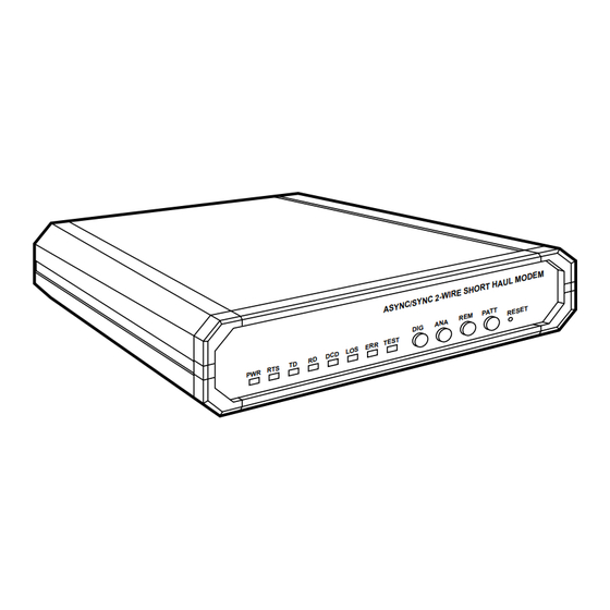
Async/Sync 2-Wire Short Haul Modem
CUSTOMER
SUPPORT
INFORMATION
T D
R T S
P W R
Order toll-free in the U.S. 24 hours, 7 A.M. Monday to midnight Friday: 877-877-BBOX
FREE technical support, 24 hours a day, 7 days a week: Call 724-746-5500 or fax 724-746-0746
Mail order: Black Box Corporation, 1000 Park Drive, Lawrence, PA 15055-1018
Web site: www.blackbox.com • E-mail: info@blackbox.com
C / S Y N
A S Y N
D I G
T E S T
E R R
L O S
D C D
R D
MARCH 1998
ME375A-R2
ME375AE-R2
ME376A-R2
ME376AE-R2
M O D E
H A U L
H O R T
I R E S
C 2 - W
T
R E S E
P A T T
R E M
A N A
M
Advertisement
Table of Contents

Related Manuals for Black Box ME375A-R2


Summary of Contents for Black Box ME375A-R2
- Page 1 Order toll-free in the U.S. 24 hours, 7 A.M. Monday to midnight Friday: 877-877-BBOX FREE technical support, 24 hours a day, 7 days a week: Call 724-746-5500 or fax 724-746-0746 SUPPORT Mail order: Black Box Corporation, 1000 Park Drive, Lawrence, PA 15055-1018 INFORMATION Web site: www.blackbox.com • E-mail: info@blackbox.com...
- Page 2 FCC/IC RFI STATEMENTS, SAFETY WARNING FEDERAL COMMUNICATIONS COMMISSION CANADIAN DEPARTMENT OF COMMUNICATIONS RADIO FREQUENCY INTERFERENCE STATEMENTS This equipment generates, uses, and can radiate radio frequency energy and if not installed and used properly, that is, in strict accordance with the manufacturer’s instructions, may cause interference to radio communication.
- Page 3 ASYNC/SYNC 2-WIRE SHORT-HAUL MODEMS NORMAS OFICIALES MEXICANAS (NOM) ELECTRICAL SAFETY STATEMENT INSTRUCCIONES DE SEGURIDAD 1. Todas las instrucciones de seguridad y operación deberán ser leídas antes de que el aparato eléctrico sea operado. 2. Las instrucciones de seguridad y operación deberán ser guardadas para referencia futura.
- Page 4 NOM STATEMENT 10. El equipo eléctrico deber ser situado fuera del alcance de fuentes de calor como radiadores, registros de calor, estufas u otros aparatos (incluyendo amplificadores) que producen calor. 11. El aparato eléctrico deberá ser connectado a una fuente de poder sólo del tipo descrito en el instructivo de operación, o como se indique en el aparato.
-
Page 5: Table Of Contents
4.2 Power-Up, Normal Operation, and Power-Down ......22 4.3 Reconfiguration ................23 5. Troubleshooting ..................24 5.1 Diagnostic Testing ................24 5.2 Calling Black Box ................28 5.3 Shipping and Packaging ..............28 Appendix: Pinouts ..................29 Legal Information ................... 33... -
Page 6: Specifications
CHAPTER 1: Specifications 1. Specifications Compliance — FCC Part 15 Subpart J Class A, DOC Class/MDC classe A Standard — T1: ANSI T1.601.1988 Interfaces — ME375 models: 2-wire telco, EIA RS-232; ME376 models: 2-wire telco, ITU-TSS (CCITT) V.35 Protocols — DTE side: Synchronous or asynchronous;... - Page 7 See the Appendix Power — From internal power supply through included or alternate 5-ft. (1.5-m) power cord: ME375A-R2, ME376A-R2: Input: 103.5 to 131.5 VAC, 47 to 63 Hz; ME375AE-R2, ME376AE-R2: Input: 207 to 253 VAC, 47 to 63 Hz; Consumption: 5 VA...
- Page 8 CHAPTER 1: Specifications Fuse — ME375A-R2, ME376A-R2: 0.1-A slow-blow; ME375AE-R2, ME376AE-R2: 0.2-A slow-blow Other Power Protection — AC/DC overvoltage-protection circuits connected through transformers to transmit and receive leads on the line side, plus special gas diodes MTBF — 75,500 hours Maximum Altitude —...
-
Page 9: Introduction
ASYNC/SYNC 2-WIRE SHORT-HAUL MODEMS 2. Introduction The Async/Sync 2-Wire Short Haul Modem (A/S2W SHM) operates synchronously or asynchronously at high speeds (600 bps to 128 Kbps) and in full duplex over one pair of dedicated telephone lines. It has a range of 3.4 miles (5.5 km) over 26-AWG wire. -
Page 10: Installation
CHAPTER 3: Installation 3. Installation This chapter tells you how to configure and install the Async/Sync 2-Wire Short Haul Modem. After you finish doing this, refer to Chapter 4 for operating information. 3.1 Placement The Async/Sync 2-Wire Short Haul Modem is designed to be placed on a tabletop, shelf, or bench, and is delivered completely assembled. - Page 11 ASYNC/SYNC 2-WIRE SHORT-HAUL MODEMS CHASS-GND CLOCK POS BAUD 0.6K 1.2K 2.4K 4.8K 9.6K 19.2K 38.4K 128K 1STB 2STB EVEN P.EN 8BIT 7BIT SYNC Figure 3-1. The A/S2W SHM’s internal controls and indicators.
- Page 12 CHAPTER 3: Installation Table 3-1. Possible Settings of Internal Controls Callout Description Position/Label Possible Factory- No. in Settings Default Fig. 3-1 Setting DIP Switch Position 1 Async or sync Sync ON = ASYNC operation OFF = SYNC Position 2 8 or 7 data bits 8 bits ON = 8BIT OFF = 7BIT...
- Page 13 †These data-rate settings are not supported by the standard A/S2W SHM. If you need to transfer data at one of these speeds, call Black Box Technical Support for a special quote on a unit that will. **These settings (popular speeds for direct computer-to-computer...
- Page 14 CHAPTER 3: Installation Table 3-1. Possible Settings of Internal Controls (cont’d.) Callout Description Function/Label Possible Factory- No. in Settings Default Fig. 3-1 Setting Clock-Source For master units, select (CLOCK) either internal timing (INT) Jumper or external timing (EXT). For slave units, always select loopback (received) timing (LBT).
-
Page 15: Connecting The Data Cables
ASYNC/SYNC 2-WIRE SHORT-HAUL MODEMS 3.3 Connecting the Data Cables To connect your data cables to the Async/Sync 2-Wire Short Haul Modem, take these steps, referring to Figure 3-2 below: 1. Connect the twisted-pair transmission line to the two clips marked LINE (or Pins 4 and 5 of the RJ-45 connector) and (optionally) the cable shield to the clip marked GND (or Pin 2 of the RJ-45 connector). -
Page 16: Connecting To Ac Power
CHAPTER 3: Installation Wire Insertion Details 1) Insert screwdriver into square hole. LINE 2) Raise inserted screwdriver, putting pressure on the ramp within the square hole. The wire clamp within the round hole will open. 3) Insert the stripped end of the wire and remove the screwdriver. - Page 17 The AC cord is fused at the rear panel of the unit. If this fuse blows, make sure you replace it only with a fuse rated for the required current and of the specified type (0.2-A slow-blow for ME375A-R2 and ME376A-R2, 0.1-A slow-blow for ME375AE-R2 and ME376AE-R2). An extra fuse should have been included with the unit.
-
Page 18: Operation
CHAPTER 4: Operation 4. Operation This chapter lists the Async/Sync 2-Wire Short Haul Modem’s external controls and indicators, describes their functions, and describes operating procedures. Complete and confirm the installation procedures described in Chapter 3 before you attempt to operate the A/S2W SHM. If you have difficulty, refer to Chapter 5. 4.1 The Front-Panel Controls and Indicators FIgure 4-1 below shows the front panel of the Async/Sync 2-Wire Short Haul Modem, including all of the controls and LED indicators mounted on it. - Page 19 ASYNC/SYNC 2-WIRE SHORT-HAUL MODEMS Table 4-1. Front-Panel Controls and Their Functions Control Function Press this Local Digital Loopback button to cause the local A/S2W SHM to loop received data and clock signals from the line back out of its own transmitter. This is equivalent to activating remote digital loopback (see below) on the remote unit.
- Page 20 CHAPTER 4: Operation Table 4-2. Front-Panel Indicators and Their Functions Indicator ITU-TSS Function (CCITT) Circuit Green LED is steadily lit while power is present. Yellow LED is steadily lit while the Request to Send (RTS) signal from the DTE is high. Yellow LED is steadily lit while the local A/S2W SHM transmits steady SPACE.
-
Page 21: Power-Up, Normal Operation, And Power-Down
LED indicators is required. If you have difficulty, perform the diagnostic tests described in Section 5.1. If you still can’t solve the problem, call Black Box as described in Section 5.2. -
Page 22: Reconfiguration
The A/S2W SHMs should begin operating with their new parameters. If there are problems, make sure that both units are set correctly. If they are, perform the diagnostic tests described in Section 5.1. If you still can’t solve the problem, call Black Box as described in Section 5.2. -
Page 23: Troubleshooting
ASYNC/SYNC 2-WIRE SHORT-HAUL MODEMS 5. Troubleshooting 5.1 Diagnostic Testing If you have problems with data communication on your Async/Sync 2-Wire Short Haul Modem system, or if you just want to verify proper system operation, the A/S2W SHM has diagnostic capabilities that can help you. You can use the A/S2W SHM’s front-panel pushbuttons to control different kinds of tests with which you can quickly check the A/S2W SHM, the attached cables (including the transmission line), and the local DTE. - Page 24 If the error goes away, the problem was probably in the old cables. Otherwise, the A/S2W SHM is probably faulty; call Black Box for technical support. If you use a BERT unit and it indicates all clear, but you get errors when you perform the DTE test, the DTE is probably the source of the problem.
- Page 25 2-wire line circuits inside one or both of the units are not operating properly. If possible, try a different line. If this is impossible, or if the problem does not go away when you use a different line, call Black Box for technical support.
- Page 26 3. When the operator at the remote site notifies you that he or she has finished, return the DIG button to the OFF position by pushing it again. If you have been unable to solve the problem, call Black Box for technical support as described in the next section.
-
Page 27: Calling Black Box
If you need to transport or ship your Async/Sync 2-Wire Short Haul Modem: • Package it carefully. We recommend that you use the original container. • Before you ship a unit for repair or return, contact Black Box to get a Return Materials Authorization (RMA) number, and make sure you include... -
Page 28: Appendix: Pinouts
APPENDIX: Pinouts Appendix: Pinouts The table below and on the following pages describes the leads and signals supported by the two models of the Async/Sync 2-Wire Short Haul Modem. ITU-TSS EIA Signal Name/ ITU-TSS Signal Name/ Description (CCITT) RS-232 Abbreviation for V.35 Abbreviation for V.24... - Page 29 ASYNC/SYNC 2-WIRE SHORT-HAUL MODEMS ITU-TSS EIA Signal Name/ ITU-TSS Signal Name/ Description (CCITT) RS-232 Abbreviation for V.35 Abbreviation for V.24 EIA RS-232 Pin(s) ITU-TSS V.35 Circuit (ME375) (ME375) (ME376) (ME376) Data Set Ready (DSR) Data Set Ready (DSR) If DIP Switch Position 7 is set to DSR, the A/S2W SHM holds this signal high unless it is in digital...
- Page 30 APPENDIX: Pinouts ITU-TSS EIA Signal Name/ ITU-TSS Signal Name/ Description (CCITT) RS-232 Abbreviation for V.35 Abbreviation for V.24 EIA RS-232 Pin(s) ITU-TSS V.35 Circuit (ME375) (ME375) (ME376) (ME376) Transmitter Signal Serial Clock Transmit A More commonly known as Element Timing [DCE] (SCT A) Transmit Clock (TXC).
- Page 31 ASYNC/SYNC 2-WIRE SHORT-HAUL MODEMS ITU-TSS EIA Signal Name/ ITU-TSS Signal Name/ Description (CCITT) RS-232 Abbreviation for V.35 Abbreviation for V.24 EIA RS-232 Pin(s) ITU-TSS V.35 Circuit (ME375) (ME375) (ME376) (ME376) Test Mode (TM) Test Mode (TM) The A/S2W SHM raises this signal during any test and any time its internal BERT is activated (the...
-
Page 32: Legal Information
LEGAL INFORMATION DISCLAIMERS No representation for fitness of this product for any purpose other than those specifically mentioned in this manual is made either by the manufacturer or its agents. The manufacturer shall not be liable for any direct, indirect, special, incidental, or consequential damages, whether based on contract, tort, or any legal theory. - Page 33 NOTES...
- Page 34 ©Copyright 1998. Black Box Corporation. All rights reserved. 1000 Park Drive • Lawrence, PA 15055-1018 • 724-746-5500 • Fax 724-746-0746...
Need help?
Do you have a question about the ME375A-R2 and is the answer not in the manual?
Questions and answers