Advertisement
Quick Links
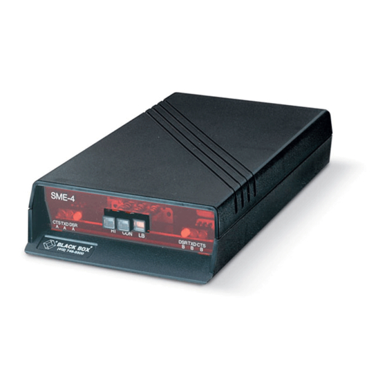
Synchronous Modem
Eliminator (SME-4M)
CUSTOMER
Order toll-free in the U.S.: Call 877-877-BBOX (outside U.S. call 724-746-5500)
FREE technical support 24 hours a day, 7 days a week: Call 724-746-5500 or fax 724-746-0746
SUPPORT
Mailing address: Black Box Corporation, 1000 Park Drive, Lawrence, PA 15055-1018
INFORMATION
Web site: www.blackbox.com • E-mail: info@blackbox.com
S M E -4
R I
D S R
C T S T X D
A
A
A
DECEMBER 2001
C T S
L B
D S R T X D
C O N
B
B
B
ME251A-R3
ME251AE-R3
ME251C-R3
ME253A-R2
ME253AE-R2
ME253C-R2
ME255A-R2
ME255AE-R2
ME255C-R2
Advertisement

Subscribe to Our Youtube Channel
Related Manuals for Black Box SME-4M ME251A-R3


Summary of Contents for Black Box SME-4M ME251A-R3
- Page 1 Order toll-free in the U.S.: Call 877-877-BBOX (outside U.S. call 724-746-5500) FREE technical support 24 hours a day, 7 days a week: Call 724-746-5500 or fax 724-746-0746 SUPPORT Mailing address: Black Box Corporation, 1000 Park Drive, Lawrence, PA 15055-1018 INFORMATION Web site: www.blackbox.com • E-mail: info@blackbox.com...
- Page 2 FCC STATEMENT FEDERAL COMMUNICATIONS COMMISSION INDUSTRY CANADA RADIO FREQUENCY INTERFERENCE STATEMENTS This equipment generates, uses, and can radiate radio frequency energy and if not installed and used properly, that is, in strict accordance with the manufacturer’s instructions, may cause interference to radio communication.
- Page 3 Synchronous Modem Eliminator (SME-4M) INSTRUCCIONES DE SEGURIDAD (Normas Oficiales Mexicanas Electrical Safety Statement) 1. Todas las instrucciones de seguridad y operación deberán ser leídas antes de que el aparato eléctrico sea operado. 2. Las instrucciones de seguridad y operación deberán ser guardadas para referencia futura. 3.
- Page 4 TRADEMARK STATEMENT TRADEMARKS USED IN THIS MANUAL Any trademarks mentioned in this manual are acknowledged to be the property of the trademark owners.
-
Page 5: Table Of Contents
Synchronous Modem Eliminator (SME-4M) Contents Chapter Page 1. Specifications ............... .5 2. -
Page 6: Specifications
CHAPTER 1: Specifications 1. Specifications AC Power — 115 VAC, 60 Hz or 230 VAC, 50 Hz, 10 watts Wallmount No load output voltage: 18 VAC nominal Transformer Output — Voltage at rated current 16 + 0.5 VAC rated Load Current 0.13 amps (part number PS154) Size —... -
Page 7: Description
Synchronous Modem Eliminator (SME-4M) 2. Description The SME-4M Synchronous Modem Eliminator is designed to replace two modems in point-to-point applications. As shown below, a single SME-4M allows asynchronous, synchronous or bisynchronous communications between two items of data terminal equipment (DTE) over EIA RS-232C cable. In the synchronous mode, the SME-4M operates at speeds up to 38,400 bps, 56,000 bps or 64,000 bps depending on the model. - Page 8 CHAPTER 2: Description PORT B PORT A Figure 2-3. Location of Controls, Indicators and Straps...
-
Page 9: Installation
Synchronous Modem Eliminator (SME-4M) 3. Installation Proceed as follows to install the SME-4M: 1. Remove the release screw located on the bottom center of the unit and separate the cover from the unit. 2. Plug in the cord from the transformer to the male power connector, J3, on the card. Do not plug the transformer into an AC outlet. - Page 10 CHAPTER 3: Installation NOTE The IBM device parameters should be set for non-switched/leasedline. If different settings are required, see steps 7 through 10. 7. Select the CTS control by installing both the “A” and “B” CTS constant/switched straps. In the switched position, a CTS signal is generated when the SME-4M receives an RTS signal (in the digital loopback test mode, the control signals always will be ON).
-
Page 11: Led Displays
Synchronous Modem Eliminator (SME-4M) 3.1 LED Displays Transmitted Data in space Transmitted Data in mark data flow from port B to port A no data flow from port B to port A data flow from port A to port B no data flow from port A to port B Data Set Ready signal ON Data Set Ready signal OFF... - Page 12 CHAPTER 3: Installation Clear To Send signal ON Clear To Send signal OFF CTS A ON indicates a CTS signal (pin 5) out from port A indicates no CTS signal (pin 5) out from port A CTS B ON indicates a CTS signal (pin 5) out from port B indicates no CTS signal (pin 5) out from port B NOTE In the CTS switched mode, the CTS LEDs also indicate the reception...
-
Page 13: Digital Loopback Test
Synchronous Modem Eliminator (SME-4M) 4. Digital Loopback Test The digital loopback test is for asynchronous applications only. Proceed as follows to initiate the test. 1. Press the loopback switch (the switch must remain in the IN position) on the front panel to loopback at the digital interfaces for both devices connected to the SME-4M. -
Page 14: Application Notes
CHAPTER 5: Application Notes 5. Application Notes PORT A PORT A SME-4M 5294 OR 5251 ASYNC 36 MODEL 12 HOST Figure 5-1. Typical IBM Application For most applications (including the one shown in Figure 5-1) the following configuration is recommended: 1. -
Page 15: Rs-232 Interface
Synchronous Modem Eliminator (SME-4M) 6. RS-232 Interface Pinning Table 6-1 RS-232 Interface Pinning CIRCUIT DESCRIPTION SIGNAL TYPE DIRECTION Protective Ground Ground — Transmitted Data Data To DCE Receive Data Data From DCE Request To Send Control To DCE Clear To Send Control From DCE Data Set Ready... - Page 16 CHAPTER 6: RS-232 Interface Pinning Table 6-1. RS-232 Interface Pinning (continued) CIRCUIT DESCRIPTION SIGNAL TYPE DIRECTION — Local Loopback Test To DCE Secondary Request Control To DCE To Send Data Terminal Ready Control To DCE Signal Quality Control From DCE Detector Ring Indicator Control...
- Page 17 Synchronous Modem Eliminator (SME-4M) NOTE The above chart shows all pins on the DB25 connector. The SME-4 only uses Pins 1 through 8, 15, 17, 20, 21, 22, and 24. SIGNAL SIGNAL DISTINATION NUMBER NUMBER DESTINATION PROTECTIVE GROUND SECONDARY TRANSMITTED DATA TRANSMITTED DATA DCE TRANSMITTER SIGNAL ELEMENT TIMING RECEIVED DATA...
-
Page 18: Nonstandard Transmission Speeds
CHAPTER 7: Nonstandard Transmission Speeds 7. Nonstandard Transmission Speeds The SME-4M can be configured to operate at some nonstandard data transmission speeds depending upon the model and the frequency of the installed crystal. To set the SME-4M for one of these different speeds, configure the unit according to the chart below. - Page 19 © Copyright 2001. Black Box Corporation. All rights reserved. 1000 Park Drive • Lawrence, PA 15055-1018 • 724-746-5500 • Fax 724-746-0746...
Need help?
Do you have a question about the SME-4M ME251A-R3 and is the answer not in the manual?
Questions and answers