Table of Contents
Advertisement
Quick Links
AUGUST 2000
ME800A Plus
ME800AE Plus
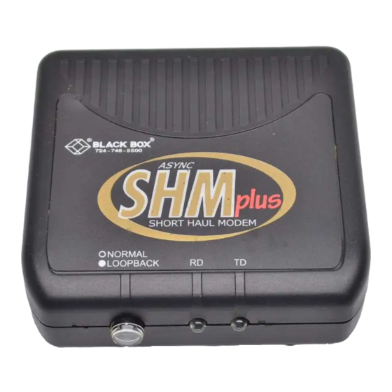
Short-Haul Modem B Plus
(SHM-B Plus Async)
CUSTOMER SUPPORT INFORMATION
Order toll-free in the U.S.: Call 877-877-BBOX (outside U.S. call 724-746-5500)
FREE technical support 24 hours a day, 7 days a week: Call 724-746-5500 or fax 724-746-0746
Mailing address: Black Box Corporation, 1000 Park Drive, Lawrence, PA 15055-1018
Web site: www.blackbox.com • E-mail: info@blackbox.com
Advertisement
Table of Contents

Related Manuals for Black Box ME800A Plus


Summary of Contents for Black Box ME800A Plus
- Page 1 Order toll-free in the U.S.: Call 877-877-BBOX (outside U.S. call 724-746-5500) FREE technical support 24 hours a day, 7 days a week: Call 724-746-5500 or fax 724-746-0746 Mailing address: Black Box Corporation, 1000 Park Drive, Lawrence, PA 15055-1018 Web site: www.blackbox.com • E-mail: info@blackbox.com...
-
Page 2: Federal Communications Commission
SHM-B PLUS ASYNC FEDERAL COMMUNICATIONS COMMISSION INDUSTRY CANADA RADIO FREQUENCY INTERFERENCE STATEMENTS This equipment generates, uses, and can radiate radio frequency energy and if not installed and used properly, that is, in strict accordance with the manufacturer’s instructions, may cause interference to radio communication. It has been tested and found to comply with the limits for a Class A computing device in accordance with the specifications in Subpart J of Part 15 of FCC rules, which are designed to provide reasonable protection against such interference... -
Page 3: Instrucciones De Seguridad
SHM-B PLUS ASYNC NORMAS OFICIALES MEXICANAS (NOM) ELECTRICAL SAFETY STATEMENT INSTRUCCIONES DE SEGURIDAD 1. Todas las instrucciones de seguridad y operación deberán ser leídas antes de que el aparato eléctrico sea operado. 2. Las instrucciones de seguridad y operación deberán ser guardadas para referencia futura. - Page 4 SHM-B PLUS ASYNC 10. El equipo eléctrico deber ser situado fuera del alcance de fuentes de calor como radiadores, registros de calor, estufas u otros aparatos (incluyendo amplificadores) que producen calor. 11. El aparato eléctrico deberá ser connectado a una fuente de poder sólo del tipo descrito en el instructivo de operación, o como se indique en el aparato.
-
Page 5: Trademarks Used In This Manual
SHM-B PLUS ASYNC TRADEMARKS USED IN THIS MANUAL Any trademarks mentioned in this manual are acknowledged to be the property of the trademark owners. -
Page 6: Specifications
SHM-B PLUS ASYNC 1. Specifications Transmission — Data Rate (bps) AWG (mm) 24 (0.5) 26 (0.4) Distance in miles 115,200 57,600 38,400 19,200 9600 4800 2400 1200 NOTE:The above specifications are valid for 24- or 26-AWG unshielded twisted-pair telephone cable insulated by polyethylene with a mutual capacitance of 0.083 pf/mile. - Page 7 SHM-B PLUS ASYNC Equipment Interface — EIA-232/CCITT V.24 interface with a hardware handshake (selected through use of an external switch). Data Carrier Detect (DCD) true (high) indicates operating short-haul modem at the remote end of the loop. Interface is switch-selectable for DTE/DCE configuration (pins 2 and 3 reversed, pins 4 and 5 reversed with pin 8, pin 6 reversed with pin 20) Connectors —...
- Page 8 SHM-B PLUS ASYNC Enclosure — High-impact plastic Power — Power is supplied by a wall-mounted power transformer. No more than 16 Vrms is present in unit. Primary: 115 VAC ±10%, 60 Hz, 5 watts (12 watts max.); Primary: 230 VAC ±10%, 50/60 Hz; Secondary: 17 VAC, 700 mA Size —...
- Page 9 SHM-B PLUS ASYNC 2. Introduction The Short-Haul Modem Model B Async Plus (SHM-B Async) is an asynchronous full-duplex 4-wire line driver/receiver which allows two EIA-232 devices to communicate at distances of up to 4 miles and at data speeds of up to 115.2 kbps. In addition to the transmitter and receiver circuits, the SHM-B Async Plus includes EIA-232 control line interfaces, status monitor LEDs, and a loopback switch.
-
Page 10: Installation
SHM-B PLUS ASYNC 3. Installation Installation involves three basic steps: four-wire connections; EIA-232 connection; switch settings. 3.1 Four-Wire Connections Connect pairs of modems using the terminal block or RJ-11 connectors provided. Figure 1 shows the location of the terminal block and the RJ-11 jack. a) TERMINAL BLOCK: Refer to Figure 2 to make the proper connections between two SHM-B units using the terminal block. - Page 11 SHM-B PLUS ASYNC LOOPBACK RS-232 RTS/DTR DTE/DCE CONNECTOR CONTROL RD LED RJ11 TERMINAL CONNECTOR BLOCK TD LED POWER CONNECTOR Figure 1. Bottom View. SHM #2 SHM #1 Figure 2. Wiring Diagram—Terminal Block.
- Page 12 SHM-B PLUS ASYNC b) RJ-11 JACK: 1. Connect pairs of modems using a crossover RJ-11 cable (refer to Figure 3). A crossover cable has the RJ-11 tabs on the same side of the cable. 2. Insert the RJ-11 cable into both local and remote modem’s jack.
- Page 13 SHM-B PLUS ASYNC 3.2 EIA-232 Connection Connect the SHM-B to your computer or terminal with a standard EIA-232 cable and DB25 connectors. Refer to your equipment’s installation manual if you need information on the exact EIA-232 signals required for your equipment. Often, it is best to use only the Transmit Data (TD), Receive Data (RD), and ground lines if your equipment does not require the use of the control signals Request To Send (RTS), Clear To Send...
- Page 14 SHM-B PLUS ASYNC 3.3 Switch Settings DTE/DCE S WITCH Refer to Figure 1 in this chapter. Switch S1 is used to reverse the TD, RD, and hardware flow control lines on the EIA-232 interface. This eliminates the need to swap these signals in your EIA-232 cables.
- Page 15 SHM-B PLUS ASYNC Table 2. Pinning with DTE/DCE switch in the DCE position. PIN NUMBER SIGNAL NAME DIRECTION Protective Ground ————— Transmitted Data TD* To DCE Received Data RD* From DCE Request to Send (RTS)* To DCE Clear to Send (CTS)* From DCE Data Set Ready (DSR)* From DCE...
- Page 16 SHM-B PLUS ASYNC 3.4 Flow Control Switch The SHM-B uses a clever, yet simple way to allow this unit to work with a broad line of equipment. EIA-232C H (RTS/DTR C TANDARD ANDSHAKING ONTROL EN P WITCH OSITION The individual SHM-B modems force their own DTR, RTS, CTS, and DSR control lines HIGH (>+3V) when: •...
- Page 17 SHM-B PLUS ASYNC negative state will also drop DCD on the remote side to a negative state. DCD will also go LOW if the remote SHM-B is powered down, or if the twisted-pair wire is broken. X-ON/X-OFF M (RTS/DTR C [S3] DIS P ONTROL...
-
Page 18: Operation
SHM-B PLUS ASYNC 4. Operation After completing the wiring and configuration procedure, connect the SHM-B to your equipment, then plug the wall transformer into its power source and into the SHM-B. Check the SHM-B operation at both ends of the loop by pressing the LOOPBACK switch, S2. (RS-232) (RS-232) SHM #1 in NORMAL mode. - Page 19 SHM-B PLUS ASYNC When in loopback mode, the switch button indicator will appear white. If a CRT terminal is connected to the SHM-B, typing characters on the keyboard should result in the same characters appearing on the CRT screen. If no characters appear, check your EIA-232 connections and the setting of S1.
-
Page 20: Troubleshooting Guide
SHM-B PLUS ASYNC 5. Troubleshooting Guide The following information will help you troubleshoot your installation if problems develop. If your particular situation isn’t listed here, call Technical Support for assistance. Have ready a description of the problem with your installation, your DTE equipment make and models, your equipment’s DTE/DCE configuration and flow control type (hardware or software), your EIA-232 cable pinouts, and what (if anything) you have already... - Page 21 SHM-B PLUS ASYNC If not, check the DCE/DTE switch on that unit. Once you get a TD LED flashing on that unit, simultaneously the RD LED should flash on the other SHM-B unit. If not, go to step 2. 2. Inspect the wiring between the two modems. Have the wires been properly installed? Transmit + (TX+) on one modem must be wired to Receive + (RX+) on the other modem;...
- Page 22 SHM-B PLUS ASYNC • remote SHM-B without power SYMPTOM: TD and RD LEDs indicate data activity, but data communication doesn’t exist. 1. Check the wiring of the EIA-232 port. Refer to Section 3.2 for information. 2. Check the setting of S1. Refer to Section 3.3 for information.
- Page 23 SHM-B PLUS ASYNC pieces of wire. Connect that SHM to a dumb terminal and key in characters; look for a good loopback. A good loopback verifies a SHM-B in proper working condition. • If you don’t have errors, you have verified a problem with the twisted-pair cable.
- Page 24 SHM-B PLUS ASYNC “crosstalk.” It may be that the data sign is jumping from the adjacent cable onto the four-wire circuit between the two SHM-B modems (another type of induced signal). • While you are checking your cable for sources of noise and crosstalk, check the cable for irregularities in the shield.
- Page 25 © Copyright 2000. Black Box Corporation. All rights reserved. 1000 Park Drive • Lawrence, PA 15055-1018 • 724-746-5500 • Fax 724-746-0746...
Need help?
Do you have a question about the ME800A Plus and is the answer not in the manual?
Questions and answers