Advertisement
Quick Links
DECEMBER 1998
ME749A-F
ME749A-M
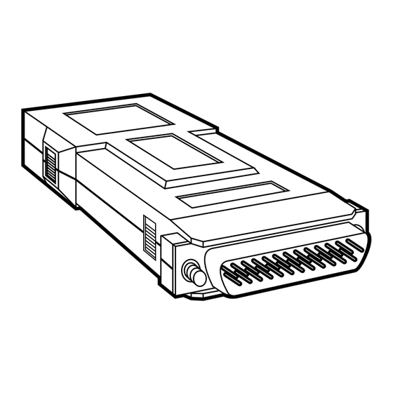
Mini Driver 4W-S
CUSTOMER SUPPORT INFORMATION
Order toll-free in the U.S. 24 hours, 7 A.M. Monday to midnight Friday: 877-877-BBOX
FREE technical support, 24 hours a day, 7 days a week: Call 724-746-5500 or fax 724-746-0746
Mail order: Black Box Corporation, 1000 Park Drive, Lawrence, PA 15055-1018
Web site: www.blackbox.com • E-mail: info@blackbox.com
Advertisement

Related Manuals for Black Box Mini Driver 4W-S


Summary of Contents for Black Box Mini Driver 4W-S
- Page 1 Order toll-free in the U.S. 24 hours, 7 A.M. Monday to midnight Friday: 877-877-BBOX FREE technical support, 24 hours a day, 7 days a week: Call 724-746-5500 or fax 724-746-0746 Mail order: Black Box Corporation, 1000 Park Drive, Lawrence, PA 15055-1018 Web site: www.blackbox.com • E-mail: info@blackbox.com...
-
Page 2: Trademarks Used In This Manual
TRADEMARKS TRADEMARKS USED IN THIS MANUAL Any trademarks mentioned in this manual are acknowledged to be the property of the trademark owners. -
Page 3: Specifications
MINI DRIVER 4W-S 1. Specifications Transmission Mode — Synchronous, full-duplex Transmission Line — Unconditioned/unloaded 4-wire (2 twisted pairs), 19 to 26 AWG Transmission Level — -6 dBm Transmission Range (miles) — Wire Gauge Speed (bps) 19,200 9600 4800 2400 1200 NOTE: Multiply by 1.6 to derive ranges in km. - Page 4 CHAPTER 1: Specifications ME749-F: (1) DB25 female Connectors — and (1) 5-screw terminal block; ME749-M: (1) DB25 male and (1) 5- screw terminal block Operating Temperature — 32 to 122°F (0 to 50°C) Humidity Tolerance — Up to 95%, noncondensing Power Supply —...
- Page 5 RS-232 standard, even when Transmit Data is constantly a MARK. The Mini Driver 4W-S is isolated from the line by balanced transformers. These transformers, together with the electronic circuitry, protect the modem against voltage transients.
- Page 6 Data is transmitted and received at a balanced imped- ance which ensures excellent immunity to circuit noise. The Mini Driver 4W-S is transformer-isolated from the telephone line to protect against voltage spikes. A typical installation is shown in Figure 1.
-
Page 7: Installation
MINI DRIVER 4W-S 3. Installation 1. Open the unit by pressing in the tabs on the side of the cover with a small screwdriver. 2. Separate the top half of the case from the bottom half. 3. Set the baud rate switch to the desired setting as shown in Table 1. - Page 8 MINI DRIVER 4W-S Figure 2. Baud Rate Setting Switch. 4. Connect the twisted-pair cable to the transmit and receive screw-terminals. See Figure 3. Figure 3. Installation Diagram. 5. Be sure that the screw locks for the RS-232 connector are in their mounting holes. Align the top cover with the bottom cover and snap them together.
- Page 9 MINI DRIVER 4W-S 6. Repeat steps 1 to 4 for the remote Mini Driver 4W-S. Make sure the local transmit terminals are connected to the remote receive terminals and that the local receive terminals are connected to the remote transmit terminals (see Figure 3).
- Page 10 © Copyright 1998. Black Box Corporation. All rights reserved. 1000 Park Drive • Lawrence, PA 15055-1018 • 724-746-5500 • Fax 724-746-0746...
Need help?
Do you have a question about the Mini Driver 4W-S and is the answer not in the manual?
Questions and answers