Advertisement
Quick Links
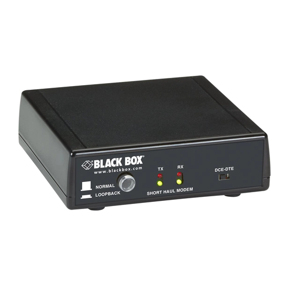
Short-Haul Modem
Product Group Title
Place a receiving device up to 4 miles from the
sending device.
Select DCE or DTE via a DIP switch, so you won't need special cables.
Order toll-free in the U.S.: Call 877-877-BBOX (outside U.S. call 724-746-5500)
Customer
FREE technical support 24 hours a day, 7 days a week: Call 724-746-5500 or fax
Support
724-746-0746 • Mailing address: Black Box Corporation, 1000 Park Drive, Lawrence,
Information
PA 15055-1018 • Web site: www.blackbox.com • E-mail: info@blackbox.com
™
codes
codes
codes
BLACK BOX
BLACK BOX
March 2009
ME800A-R4
codes
codes
codes
®
®
Advertisement

Subscribe to Our Youtube Channel
Related Manuals for Black Box ME800A-R4


Summary of Contents for Black Box ME800A-R4
- Page 1 Order toll-free in the U.S.: Call 877-877-BBOX (outside U.S. call 724-746-5500) Customer FREE technical support 24 hours a day, 7 days a week: Call 724-746-5500 or fax Support 724-746-0746 • Mailing address: Black Box Corporation, 1000 Park Drive, Lawrence, Information PA 15055-1018 • Web site: www.blackbox.com • E-mail: info@blackbox.com...
- Page 2 Trademarks Used in this Manual Trademarks Used in this Manual Black Box and the Double Diamond logo are registered trademarks of BB Technologies, Inc. UL Is a registered trademark of Underwriters Laboratories. Any other trademarks mentioned in this manual are acknowledged to be the property of the trademark owners.
- Page 3 FCC and IC RFI Statements/NOM Statement FEDERAL COMMUNICATIONS COMMISSION AND INDUSTRY CANADA RADIO FREQUENCY INTERFERENCE STATEMENTS This equipment generates, uses, and can radiate radio-frequency energy, and if not installed and used properly, that is, in strict accordance with the manufacturer’s instructions, may cause inter ference to radio communication. It has been tested and found to comply with the limits for a Class A computing device in accordance with the specifications in Subpart B of Part 15 of FCC rules, which are designed to provide reasonable protection against such interference...
- Page 4 NOM Statement 5. El aparato eléctrico no deberá ser usado cerca del agua — por ejemplo, cerca de la tina de baño, lavabo, sótano mojado o cerca de una alberca, etc. 6. El aparato eléctrico debe ser usado únicamente con carritos o pedestales que sean recomendados por el fabricante.
- Page 5 NOM Statement 17. Cuidado debe ser tomado de tal manera que objectos liquidos no sean derramados sobre la cubierta u orificios de ventilación. 18. Servicio por personal calificado deberá ser provisto cuando: A: El cable de poder o el contacto ha sido dañado; u B: Objectos han caído o líquido ha sido derramado dentro del aparato;...
- Page 6 Table of Contents Table of Contents 1. Specifications ....................7 2. Introduction ....................8 3. Installation ....................10 4. Troubleshooting ..................15 Page 6 724-746-5500 | blackbox.com...
-
Page 7: Specifications
Chapter 1: Specifications 1. Specifications Technical Specifications Approvals Power supply: UL , CSA ® Data Flow Control: X-ON/X-OFF; Data Format: Asynchronous, full-duplex Interconnect Two-pair twisted-pair cable Speed Up to 115,200 bps at up to 4000 feet (1250 m); Up to 57,600 bps at up to 1 mile; Up to 9600 bps at up to 4 miles User Controls (1) 4-position DIP switch,... -
Page 8: Introduction
Chapter 2: Introduction 2. Introduction These short-haul modems enable you to place a receiving device up to four miles from the sending device. They are switch-selectable for either DCE or DTE application, eliminating the need for special cables and preventing confusion during installation. - Page 9 Chapter 2: Introduction Table 2-1. Components. Number Component Description Pushbutton Press this button for Loopback operation. The button is not pressed in Normal operation. (2) TX LEDs This dual Red/Green LED will be green when the Received Data is low, and red when the Received Data is high. (2) RX LEDs This LED can be used to verify proper polarity of the interconnecting lines: it should be green when no...
-
Page 10: Installation
Chapter 3: Installation 3. Installation Before you begin, make sure all equipment, including the converters, are not powered on. 1. Set the 4-position DIP switch as appropriate for local control signal enable and cable distance. 2. Set the slide switch for either DCE to connect to a PC or DTE to connect to a modem. - Page 11 Chapter 3: Installation Table 3-2. RJ-11 connector Position Function No connection No connection Table 3-3. DB9 RS-232 connector Pin–Signal DCE Interface Function DTE Interface Function (S1-A) (S1-B) 1 - Data Carrier Output Input Detect 2 - Received Data Output Input 3 - Transmitted Input Output...
- Page 12 Chapter 3: Installation NOTES (continued): 2. When configured as DCE, Data Terminal Ready and Request to Send signals may be used to disable the line driver (see S3). The remote unit will sense this condition and its Data Carrier Detect signal will become negative. 3.
- Page 13 Chapter 3: Installation Figure 3-1. Loopback function. Table 3-6. S3 switch (UP is OFF, DOWN is ON). Switch Position Hardware Control Enable (Note 1) Disabled Line Distance (Note 2) Short (less than 1000 ft.) Reserved NOTES: 1. When hardware control is enabled, both control input signals must be high for transmission to be enabled.
- Page 14 Chapter 3: Installation Table 3-7. Indicators. Indicator Function The Green LED is on when the Receive Data is low, and the Red LED is on when the Receive Data is high. This LED can be used to verify proper polarity of the interconnecting lines: it should be green when no data is being transmitted.
-
Page 15: Troubleshooting
Chapter 4: Troubleshooting 4. Troubleshooting If the units fail to operate, check the following before calling for technical support. 1. Are the units powered on? Check to see if the power supplies are plugged into a working AC outlet. 2. Check to see if the interconnect wire is connected properly, TX+ to RX+, TX- to RX-, at both ends. - Page 16 724-746-5500 or blackbox.com. About Black Box Black Box provides an extensive range of networking and infrastructure products. You’ll find everything from cabinets and racks and power and surge protection products to media converters and Ethernet switches all supported by free, live 24/7 Tech support available in 30 seconds or less.
Need help?
Do you have a question about the ME800A-R4 and is the answer not in the manual?
Questions and answers