Table of Contents
Advertisement
Quick Links
Advertisement
Table of Contents

Related Manuals for Robe Colormix 240 AT


Summary of Contents for Robe Colormix 240 AT
- Page 1 USER MANUAL ROBE ® Show Lighting s.r.o. Czech Republic www.robe.cz...
-
Page 3: Table Of Contents
Table of contents 1. Safety instructions ......................4 2.Operating determinations ....................4 3. Description of the device ....................5 4. Installation ........................6 4.1 Fitting/Exchanging the lamp ..................6 4.2 Lamp adjustment ....................... 6 4.3 Installation of the barn-doors ..................6 4.4 Manually adjusment of the beam angle .............. -
Page 4: Safety Instructions
CAUTION ! Keep this device away from rain and moisture! Unplug mains lead before opening the housing! FOR YOUR OWN SAFETY, PLEASE READ THIS USER MANUAL CAREFULLY BEFORE YOU INITIAL START - UP! 1. Safety instructions CAUTION ! Be careful with your operations.With a dangerous voltage you can suffer a dangerous electric shock when touching the wires This device has left our premises in absolutely perfect condition. -
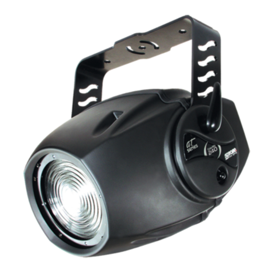
Page 5: Description Of The Device
Always fix the fixture with an appropriate safety-rope. Only operate the fixture after having checked that the housing is firmly closed and all screws are tightly fastened. The lamp must never be ignited if the fresnel-lens or any housing-cover is open, as discharge lamps may explose . The maximum ambient temperature t must never be exceeded. -
Page 6: Installation
4. Installation 4.1 Fitting/Exchanging the lamp DANGER ! Install the lamp with the device switched off only. Unplug from mains before ! Lamp cover screws „A, B, C” 3 fastening screws To insert the lamp MSD 250W/2 open the small cover at the rear of the projector by loosening the 3 screws „X, Y, Z” on the lamp cover. -
Page 7: Manually Adjusment Of The Beam Angle
4.4 Manually adjusment of the beam angle The lens system can be configured in the range between 8° and 22° beam angles.To set the desired beam angle,remove the barn-doors (if they Adjusting screw are installed) by loosening the 2 fastening screws and open the front cover by loosening the 4 quarter turn fasteners, loose the 2 adjusting screws(with Quarter turn fasteners... -
Page 8: Connection To The Mains
Overhead installation. The mounting bracket provides 3 holes (a diameter of 13 mm) and 2 quarter-circle slots. To adjust the inclination-angle,loosen the 2 adjusting screws.Turn the projector to the desired angle and retighten the adjusting screws. For overhead use, always install a safety rope that can hold at least 10 times the weight of the fixture. Pull the safety rope through the mounting bracket and over the trussing system etc. -
Page 9: Dmx- 512 Connection, Master/Slave Connection
The occupation of the connection-cables is as follows: Cable (EU) Cable (US) International Brown Black Live Light blue White Neutral Yellow/Green Green Earth Do not connect the projector to a dimmer system! 4.7 DMX- 512 connection, master/slave connection Controller operation Master/slave operation The wires must not come into contact with each other, otherwise the fixtures will not work at all, or will not work properly. -
Page 10: Dmx Protocol - 8 Bit
5. DMX Protocol - 8 bit Mode 1 Mode 2 Value Function Type of control Channel Channel Lamp On/Off, control of fans 0 -127 From max. to min. speeed of fans proportional 128-139 Lamp On after 3 seconds, reset step 140-229 No function step... -
Page 11: Controller Mode
The ColorMix 240 AT is to be operated with a MSD 250W/2 GY-9,5 lamp. A relay inside of the ColorMix 240 AT allows you to switch on and off the lamp via the control panel on the top side of the projector or via your controller without affecting the rest of the lighting. -
Page 12: Functions Of The Control Panel
The master fixture starts simultaneous program start in the other slave fixtures. All fixtures have a definite, synchronized starting point when playing back their programs.The number of running program is the same in all slaves and depends on the master's choice (menu „St.AL.”). Every fixture runs its program repeatedly, starting the program step No.1 when requested by the master. -
Page 13: Slave Control
- DMX addressing 1. Press the [Mode] - button so many times until the display shows message „A001” (with actually stored address). 2. Press [Enter] - button and use the [Up] and [Down ] buttons to select „dM.Ad.”- menu. 3. Press [Enter] - button (the letter „A” flashes) and by [Up] and [Down] buttons select required address (001 - 501), press [Enter] - button to confirm. -
Page 14: Dmx Values
[Up] and [Down]-button and press the [Enter]-button. - Lamp strikes - By this option you can read the total number of the lamp strikes since the ColorMix 240 AT has been fabricated.Press [Enter] or [Mode] to return to the menu. -
Page 15: Personality Options
- 8.4 Personality options These options allow you to modify ColorMix 240 AT operating behavior. Press [Up] and [Down] buttons to select the desired option and press [Enter] to set the value or to see next submenu. - Page 16 - Lamp Off via DMX This function allows you to switch off the lamp by DMX. Use the [Up] and [Down] buttons to select „On” if you want to switch off the lamp by DMX or „Off” if you don’t want to switch off the lamp by DMX and press [Enter] to confirm or [Mode] to cancel and return to the menu.
- Page 17 - Fan speed operating modes By using this function you can choose 5 types of the fan speed operating modes. Browse through this menu by the pressing [Up] and [Down] buttons - the display shows step by step these messages: „Auto, HIGH, reG, LoOF, LoHI”. Press [Enter] if you wish to select one of them or [Mode] to cancel and return to the menu.
-
Page 18: Switching On/Off The Lamp
This function allows you to run a special demo-test sequences without an external controller, which will show you some possibilities of using ColorMix 240 AT. Press [Enter]-button to run the test.If the test program is running, messages „run/ test” blink on the display. - Page 19 (playing is forced by the master). - Editing program This menu item allows you to select a program to edit or create.The ColorMix 240 AT has one built-in program („tESt”) and the 3 free programs, each up to 99 steps.
-
Page 20: Reset Function
The editting programs „PrG.1, PrG.2, PrG.3” are saved in the current modified fixture (master or slave1-9). - 8.8 Reset function Press [Enter] button to run a reset. This option enables the ColorMix 240 AT to index all effects (functions) and return to their standard positions. -
Page 21: Error And Information Messages
9. Error and information messages HEAt This message appears if you try to switch on the lamp within 5 minutes after having switched it off (the lamp is too hot). The message will appear on the display if the lamp doesn't ignite within 28 seconds. The fixture will store this information and automatically ignite the lamp when the 5 minutes period has expired. - Page 22 3 freely programmable programs (99 steps each) Digital serial input DMX-512 2 DMX channel-presettings (8 bit protocols): Channel Mode 1 (default) Mode 2 Lamp On/Off, reset Lamp On/Off, reset No function Cyan Cyan Magenta Magenta Yellow Yellow Speed of CMY Speed of CMY Colour macros Colour macros...
-
Page 23: Maintenance And Cleaning
Dimensions (mm) 11. Maintenance and cleaning The operator has to make sure that safety-relating and machine-technical installations are inspected by an expert after every four years in the course of an acceptance test. The operator has to make sure that safety-relating and machine-technical installations are inspected by a skilled person once a year. -
Page 24: Appendix 1 - Menu Map
12. Appendix 1 - Menu map Deffault settings=Bold print Menu Menu Menu Menu Menu Menu DESCRIPTION Level 1 Level 2 Level 3 Level 4 Level 5 Level 6 A001- dM.Ad. DMX addresss A502 d.Abl. Disable master/slave A001 MASt. Set fixture as a master MA.SL. - Page 25 Menu Menu Menu Menu Menu Menu DESCRIPTION Level 1 Level 2 Level 3 Level 4 Level 5 Level 6 Lamp power ON LAMP A001-A500 Lamp power OFF Run demo tESt Enable the sound control of the run. programs Audi Disable the sound control of the run.programs No program runs after switching fixture on tESt Test program runs after switching fixture on...
-
Page 26: Appendix 2 - Changing The Power Supply Settings
13. Appendix 2 - Changing the power supply settings Both the transformer and the ballast must be connected correctly for the local AC voltage and frequency. The wrong settings can cause poor performance or demage of the moving head. The factory settings are printed next to the power switch.
Need help?
Do you have a question about the Colormix 240 AT and is the answer not in the manual?
Questions and answers