Table of Contents
Advertisement
Advertisement
Table of Contents

Related Manuals for D.A.S. AERO-38 series


Summary of Contents for D.A.S. AERO-38 series
- Page 1 AERO-38 series Manual del Usuario / User’s Guide...
- Page 2 AERO-38A / AERO-38 ® AERO-218A / AERO-218Sub D.A.S. Audio s.a. AERO-182A / AERO-182 Precauciones de seguridad Safety Precautions El signo de exclamación dentro de un triángulo indica la The exclamation point inside an equilateral triangle indicates the existencia de componentes internos cuyo reemplazo puede existence of internal components whose substitution may affect afectar a la seguridad.
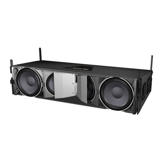
- Page 3 The model AERO-38 includes two 12GNC 1. SYSTEM DESCRIPTION 12” cone transducer with 4” EFW voice coils and The D.A.S. Audio AERO series offers two Neodymium magnet assemblies in a bass-reflex units for applications requiring precise control of the configuration. Two 10LMN16, 10” speakers arranged vertical coverage and high sound pressure levels.
- Page 4 Absolutely no risks should be taken with 2. RIGGING SYSTEM regards to public safety. When flying enclosures from ceiling support structures, extreme care should be 2.1WARNING taken to assure the load bearing capabilities of the This manual contains needed information for structures so that the installation is absolutely safe.
- Page 5 For flying boxes and defining the splay B) Chain hoists angle, the pins must be inserted in the slot of guide 2, stacked G2A48, whereas for stacking ( ), the pin goes All units in a column will be flown from the through the top hole of the guide.
- Page 6 D) PL-48S AX-AERO48 The PL-48S platform is a valuable accessory which allows up to 4 AERO-38 units to be transported in a stacked position, ready to be flown. The PL-48S is made from steel and has 4 heavy duty casters with locking brakes.
- Page 7 SPLAY ANGLES USING THE AX-COMBO Pins F) QUICK RELEASE PINS Each cabinet includes 6 steel heavy duty quick release pins stored on the rear panel of the cabinets. Both systems AERO-38, and AERO-182 can Pins can be used to be flown using steel structures located on boths sides free the pieces of the cabinets.
- Page 8 3. SELF-POWERED SYSTEMS 2.3 SAFETY FACTORS The safety factor is defined as the 3.1 AERO-38A coefficient between the breaking load limit and the The Aero-38A is a three way, class D, self maximum safe working load limit (SWLL). In this powered system.
- Page 9 3.2 AERO-182A 3.3 AERO-218A Low frequency mono-amplified system. The Aero-218A is a low frequency mono- Nominal amplifier power (RMS) 1000W. amplified system. Nominal amplifier power (RMS) 2 x 1000W. Amplifier panel description: LIMIT mplifier limiter indicator lights. When lit, the level of the signal source should be reduced.
- Page 10 3.6 SWITCH ON-OFF 3.9 ECUALIZATION The units do not need extreme EQ. Avoid A sound system should be switched on high levels of gain on the equalizers. Gain values sequentially. Switch on the self-powered unit last in above +6 dB on a console's EQ are not your sound system.
- Page 11 As can be seen in the diagram, independent signal lines exist for the subwoofer units, AERO-182A. The signal that goes to the subs is processed by means of the DSP-1Sub to adjust the delay between both systems. 3.12 RAIN PROTECTOR Electronic devices can be damaged when exposed to water or moisture.
- Page 12 3.13 HOW TO MAKE A PASSIVE The four M4x30 DIN 7985 must be screwed SYSTEM INTO A SELF POWERED ONE. in the four holes that can be seen on the radiator area. AERO-38 -->AERO-38A: The white arrows in the picture above point to the mentioned holes.
- Page 13 AERO-218Sub -->AERO-218A NOTE: As AERO-218A and AERO 182A amplifiers' polarity is inverted referenced to that of To make a passive system into an active conventional external amplifiers, the polarity of the one, firstly the back plate must be removed by speakers' wires must be changed when switching unscrewing the 12 M4x20 DIN965.
- Page 14 faston The large 6.3mm wide terminal should be attached to the black wire, and the small faston 4.8mm wide terminal should be attached to the red wire: In the case of the AERO-218A the same process applies to the second amplifier in the box. Should you have any problem during this process do not hesitate to contact D A S factory or .
- Page 15 3.14 TROUBLESHOOTING PROBLEM CAUSE SOLUTION No sound from the unit. 1- The signal source is sending 1- Check that the mixer or sound SIGNAL presence LED no signal. source is sending signal to the UNIT. indicator(s) do(es) not light up. 2- Defective cable.
- Page 16 4.3 ASSEMBLING AN ARRAY “ONE 4. ASSEMBLING AN ARRAY BY ONE” 4.1TRANSPORTING THE CABINETS When few units are to be used (minimum systems recommended is 6 units) or when the dolly AERO-38 units can be transported by using platforms cannot be used due to a lack of space, the the front panel dolly PL-38 or by using the PL-48S steel enclosures will have to be hung “one by one”.
- Page 17 Lifted by way of the rear hoist until the wheels of the PL-38 dolly platform are off the ground. Swing the G2A48 guide into place and secure it with the safety pin. Lift with the front hoist until the box is in a horizontal position.
- Page 18 4.4 ASSEMBLING AN ARRAY USING THE PL-38 PLATFORM The PL-38 platform can be used to easily transport AERO-38 units to the assembling area. To use this method of assembling and hoisting the array, there must be enough space to permit linking all the boxes from the front of the the rigging hardware.
- Page 19 Once the first box is attached to the Rear hoist!! structure, the remaining boxes should be brought to the array and attached repeating the previous steps (1 and 2) using G1A48 guides and safety pins per side making sure that the pins have been inserted and locked correctly.
- Page 20 Aero-38 Manual del usuario/ User´s manual...
- Page 21 To lower the system, both hoists should be The PL-48S platform has two types of used until the lowest box is about 1 meter from the moving pieces. One of them is fixed (PL-48S_2) and ground. From there on, only the front hoist should be can only be swung around, the other is free (PL- used so that the array assembly begins to lean 48S_1) and is joined to the platform by way of a safety...
- Page 22 Release the PL-48S_2 piece by removing Turn the piece G2A48 the safety pins (1). Next, swing the pieces and few degrees to allow fixing introduce them (2) into the rear rigging hardware of PL-48S_2 to the rigging system the lowest box, securing them with the safety pin (3). G2A48 Quick release pin must be inserted...
- Page 23 Boxes 4-5 should be separated at the front by removing the safety pins (10) that secure the G1A48 guides. The first group of boxes has now been freed When the G1A48 pieces have been freed, and is stacked safely on the PL-48S platform. To move they should be turned (11) and stored (12) within the the stack, slightly raise the upper group of boxes and corresponding box, in this case number 4, using the...
- Page 24 The next step is to roll under the remaining The last step consists of lowering the boxes, an empty PL-48S and lower the boxes until remaining array so that the safety pins can be inserted they are within close proximity of the platform. The (18) into the holes of the PL-48S_1 pieces and the procedure should now be repeated, freeing the PL- platform.
- Page 25 The arrangement in the following picture is an unstable one. The smaller the splay angle between cabinets, the more the stability. Obviously, the most reliable stack in terms of stability is the one when the splay angle between all of the cabinets is 0º. -1.6º...
- Page 26 Now the entire cluster can be lowered so the PL-48S_1 pieces get into reach of the platform. The next step is to fix the PL-48S_2 pieces to the rear rigging hardware of the box. In order to do so, the platform should be raised up (6) till the bottom hole in the rigging hardware and the hole in the PL-48S_2 match together.
- Page 27 Lower the cluster till the platform is resting on the floor. When the boxes are flown the safety pins must be inserted in the G2A48 slots. Now we want to stack the boxes, so the next step is to release the pins from the slots and introduce them in the G2A48 holes.
- Page 28 4.8º Safety pins can now be inserted (14). In this example, the set up angle between boxes 3 and 4 is 4.8º. It is important to check that pins cannot be removed by pulling outward and that they have been inserted in the G2A48 hole instead of the guide slot.
- Page 29 In order to set up the angle between boxes 1 and 2 you must pull up (23) from the grid until the hole in the G2A48 piece fits with the hole that determines the stacking angle. Then insert the safety pins (24). 1.6º...
- Page 30 In order to attach the box on top to the grid, 4.6 ASSEMBLING A CLUSTER USING THE PL-48S PLATFORM front guides G1A48 and rear guides G2A48 must be swung (2) and inserted into the AX-AERO48 grid AERO-38 boxes can be easily transported in receiving points.
- Page 31 The angles that can be seen in the example are 0.8º between the first and second boxes, and 1.6º between the second and the third boxes. The cluster can now be lifted by the two motors, and the PL-48S platform detached. The first step to detach the PL-48S platform from the bottom box is to release (6) the safety pins which secure the PL-48S_1 piece to the platform and...
- Page 32 Place the remaining group of boxes under the cluster, then lower the cluster until both front sides are in close proximity. G1A48 front guides (9) of the first box on the platform can now be swung and left in the upright position, ready to be inserted into the front rigging hardware of the next box.
- Page 33 With the front guides correctly secured, From here on, the process is similar to the swing the G2A48 (11) rear guides belonging to the previously described. Detach the safety pins from box on top of the second group and lower the grid till their receptacles on the sides of the boxes, swing (12) the guides fit into the rigging hardware of the next the G2A48 rear guides, place them into the rigging...
- Page 34 5. SUBWOOFER UNITS Externally amplified systems: An AERO-38 unit can reproduce frequencies as low as 60Hz. AERO-218Sub is the D A S recommended . . . subwoofer unit to be used along AERO-38 when subwoofers have to be ground stacked. When subwoofers are to flown, AERO 182...
- Page 35 6. MAINTENANCE The following is a discussion on how to access each transducer for maintenance or repair. In order to access the amplifier please refer to 3.11 section in this user's guide. In order to access de 12” speakers, you must first remove the front grill.
- Page 36 Internal conne ions in the AERO-38 system. In order to access the speakers in the AERO 182 and AERO 218Sub subwoofer units, first the grill must be removed from the box. Being AERO 182 and AERO 218Sub double 18” speakers, both speakers are connected in parallel mode resulting in a total impedance of 4Ohm.
- Page 37 7. SPECIFICATIONS SPECIFICATIONS Powered Systems SPECIFICATIONS Non-Powered Systems Model Aero 38A Model Aero 38 Nominal LF Amplifier Power 1000 W (Class D) Frequency Range (-10 dB) 60 Hz-18 kHz Nominal MF Amplifier Power 500 W (Class D) Horizontal Coverage (-6dB) 90º...
- Page 38 Powered Systems Non-Powered Systems SPECIFICATIONS SPECIFICATIONS Aero 218A Model Aero 218 Sub Model Nominal LF Amplifier Power 2 x 1000 W (Class D) Frequency Range (-10 dB) 28 Hz-85 Hz Input Type Balanced Differential Line RMS (Average) Power Handling 1400 W Input Impedance On-Axis Sensitivity 1 W / 1 m Line: 25 kohms...
- Page 39 8.2 LIMITER SETTINGS 8. SIGNAL PROCESSING The use of the DSP-3VS digital processor is The following formulas can be used to establish the highly recommended when running the AERO-38 limiter voltage: sound system, and the use of the DSP-1Sub when running the AERO-218Sub (AERO-182).
- Page 40 aero-38 (external amplification system) CONFIGURATION 1 aero aero 16 x -38 + 8 x -182 DSP-3VS DSP-1Sub LINE IN a a ero- ero- a a ero- ero- OPERATING PARAMETERS AMPLIFIERS WITH EQUAL GAIN USED HIGH GAIN 0 dB -2 dB -9 dB POLARITY Normal...
- Page 41 aero-38 (external amplification system) CONFIGURATION 2 aero aero 16 x -38 + 8 x -218sub DSP-3VS DSP-1Sub LINE IN aero- ero- 21 8 21 8SUB a a ero- ero- OPERATING PARAMETERS AMPLIFIERS WITH EQUAL GAIN USED HIGH GAIN 0 dB -2 dB -9 dB POLARITY...
- Page 42 aero-38A (self powered system) CONFIGURATION 1 aero aero -38a + 4 x -182a aero-38A (self powered system) CONFIGURATION 2 aero aero 16 x -38a + 4 x -182a DSP-1Sub a a ero- ero- 115V max. 3 units in parallel WARNING! AC CONNECTIONS 230V max.
- Page 43 aero-38A (self powered system) CONFIGURATION 3 aero aero 16 x -38a + 8 x -218a a a ero- ero- WARNING! 115V max. 3 units in parallel AC CONNECTIONS 230V max. 6 units in parallel a a ero-218 ero-218 POWER INPUT POWER POWER INPUT...
- Page 44 APPENDIX LINE CONNECTION: UN-BALANCED AND BALANCED. There are two basic ways to transport an audio signal with microphone or line level: Un-balanced line: Utilizing a two-conductor cable, it transports the signal as the voltage between them. Electro-magnetic interference can get added to the signal as undesired noise. Connectors that carry un-balanced signals have two pins, such as RCA ( Phono ) and ¼”...
- Page 45 D.A.S. AUDIO, S.A. C/. Islas Baleares, 24 - 46988 Fuente del Jarro - Valencia, SPAIN Tel. Intl. +34 96 134 0860 - Fax. Intl. +34 96 134 0607 D.A.S. AUDIO of AMERICA, Inc. Sunset Palmetto Park - 6816 NW 77th Court - Miami, FL 33166 U.S.A. TOLL FREE: 1-888DAS4USA Tel.
Need help?
Do you have a question about the AERO-38 series and is the answer not in the manual?
Questions and answers