Table of Contents
Advertisement
Available languages
Available languages
Quick Links
Advertisement
Chapters
Table of Contents
Troubleshooting

Related Manuals for KOBE CH7936SQB


Summary of Contents for KOBE CH7936SQB
- Page 1 KOBE Brand Range Hood Model No. / N de modèles / Modelo No. CH7930SQB CH7936SQB CH7942SQB CH7948SQB CH-179 SERIES – 9” HEIGHT INSTALLATION INSTRUCTIONS AND OPERATION MANUAL MANUEL D'INSTALLATION ET MODE D'EMPLOI INSTRUCCIONES DE INSTALACIÓN Y MANUAL DE OPERACIÓN...
- Page 2 [ENGLISH] ... 1 [FRENCH] ... 34 [SPANISH] ... 67...
-
Page 3: Table Of Contents
[ENGLISH] - READ AND SAVE THESE INSTRUCTIONS - CONTENTS IMPORTANT SAFETY INSTRUCTIONS... 2 COMPONENTS OF PACKAGE... 4 INSTALLATION ... 5 OPERATING INSTRUCTIONS... 18 MAINTENANCE ... 19 SPECIFICATIONS... 21 MEASUREMENTS & DIAGRAMS... 22 PARTS LIST ... 24 CIRCUIT DIAGRAM ... 27 TROUBLE SHOOTING ... -
Page 4: Important Safety Instructions
KOBE RANGE HOODS authorized agents will automatically void the warranty. KOBE RANGE HOODS will not be held responsible for any damages to personal property or real estate or any bodily injuries whether caused directly or indirectly by the range hood. - Page 5 What to Do In The Event Of a Range Top Grease Fire • SMOTHER FLAMES with a tight fitting lid, cookie sheet, or metal tray, and then turn off the burner. KEEP FLAMMABLE OR COMBUSTIBLE MATERIAL AWAY FROM FLAMES. If the flames do not go out immediately, EVACUATE THE AREA AND CALL THE FIRE DEPARTMENT or 911.
-
Page 6: Components Of Package
3 (42” & 48”) {G} Bottom Casing – 2 FOR MORE INFORMATION, PLEASE VISIT OUR W EBSITE CONTACT KOBE RANGE HOODS AT (626) 775-8880. Duct Cover Box (Sold Separately) {H} Adjustable Duct Cover - 1 {I} Screws Package – 1 {J} Duct Cover-Mounting Bracket –... -
Page 7: Installation
INSTALLATION PLEASE READ ENTIRE INSTRUCTIONS BEFORE PROCEEDING Calculation before Installation To calculate installation, please refer to TABLE 1. (All calculation in inches.) TABLE 1 A = Height of Floor to Ceiling B = Height of Floor to Counter Top (Standard: 36") C = Preferred Height of Counter Top to Hood Bottom (Minimum 27"... -
Page 8: Safety Warning
SAFETY WARNING HOOD MAY HAVE VERY SHARP EDGES; PLEASE WEAR PROTECTIVE GLOVES IF REMOVING ANY PARTS FOR INSTALLING, CLEANING OR SERVICING. NOTE: BE CAREFUL WHEN USING ELECTRICAL SCREWDRIVER, DAMAGE TO THE HOOD MAY OCCUR. Installation Contents UNDER THE CABINET Top Vent………………………………………………………………………………… Rear Vent……………………………………………………………………………….. -
Page 9: Under The Cabinet Installation - Top Vent
UNDER THE CABINET INSTALLATION – TOP VENT Preparation before Installation NOTE: TO AVOID DAMAGE TO YOUR HOOD, PREVENT DEBRIS FROM ENTERING THE VENT OPENING. Decide the location of the venting pipe from the hood to the outside. Refer to Figure 1. A straight, short venting run will allow the hood to perform more efficiently. - Page 10 Hood Installation CAUTION: If required to move the cooking range to install the hood, turn off the power on an electric range at the main electrical box. SHUT OFF THE GAS BEFORE MOVING A GAS RANGE. Puncture the knockout holes on the hood as shown in Figure 4. If necessary, arrange the electrical wires to run through the 1”...
-
Page 11: Under The Cabinet Installation - Rear Vent
UNDER THE CABINET INSTALLATION – REAR VENT Preparation before installation NOTE: TO AVOID DAMAGE TO YOUR HOOD, PREVENT DEBRIS FROM ENTERING THE VENT OPENING. Decide the location of the venting pipe from the hood to the outside. Refer to Figure 6. A straight, short venting run will allow the hood to perform more efficiently. - Page 12 Hood Installation CAUTION: If required to move the cooking range to install the hood, turn off the power on an electric range at the main electrical box. SHUT OFF THE GAS BEFORE MOVING A GAS RANGE. Puncture the knockout holes on the hood as shown in Figure 10. Unscrew and remove the multi duct exhaust.
- Page 13 WALL MOUNT INSTALLATION – TOP VENT ***This installation only applied with the purchase of a duct cover. Preparation before Installation NOTE: TO AVOID DAMAGE TO YOUR HOOD, PREVENT DEBRIS FROM ENTERING THE VENT OPENING. Decide the location of the venting pipe from the hood to the outside. Refer to Figure 13. A straight, short venting run will allow the hood to perform more efficiently.
- Page 14 If necessary, attach two rubber stands (provided) with two (4x8 mm) screws (provided) to the back of the hood. Attach the hood-mounting bracket to the back of the hood with nine (3/16" x 3/8") screws (provided) as shown in Figure 16. Hood Installation CAUTION: If required to move the cooking range to install the hood, turn off the power on an electric range at the main electrical box.
- Page 15 Duct Cover Installation Mark the position of the duct cover-mounting bracket. Use reference E from Table 2 and measurements on Page 22-23. Attach and secure duct cover-mounting bracket with two screws (not provided). Refer to Figure 18. NOTE: Inner duct cover will cover the duct cover-mounting bracket.
- Page 16 WALL MOUNT INSTALLATION – REAR VENT ***This installation only applied with the purchase of a duct cover. Preparation before Installation NOTE: TO AVOID DAMAGE TO YOUR HOOD, PREVENT DEBRIS FROM ENTERING THE VENT OPENING. Decide the location of the venting pipe from the hood to the outside. Refer to Figure 21. A straight, short venting run will allow the hood to perform more efficiently.
- Page 17 If necessary, attach two rubber stands (provided) with two (4x8 mm) screws (provided) to the back of the hood. Attach the hood-mounting bracket to the back of the hood with nine (3/16" x 3/8") screws (provided) as shown in Figure 25. Hood Installation CAUTION: If required to move the cooking range to install the hood, turn OFF the power on an electric range at the main electrical box.
- Page 18 Duct Cover Installation Mark the position of the duct cover-mounting bracket. Use reference E from Table 2 for references. Attach and secure duct cover-mounting bracket with two screws (not provided). Refer to Figure 27. NOTE: Inner duct cover will cover the mounting bracket. Connect electrical wires.
- Page 19 Wiring to Power Supply SAFETY WARNING RISK OF ELECTRICAL SHOCK. THIS RANGE HOOD MUST BE PROPERLY GROUNDED. MAKE SURE THIS IS DONE BY SPECIALIZED ELECTRICIAN IN ACCORDANCE WITH ALL APPLICABLE NATIONAL AND LOCAL ELECTRICAL CODES. BEFORE CONNECTING WIRES, SWITCH POWER OFF AT SERVICE PANEL AND LOCK SERVICE PANEL TO PREVENT POWER FROM BEING SWITCHED ON ACCIDENTALLY.
-
Page 20: Operating Instructions
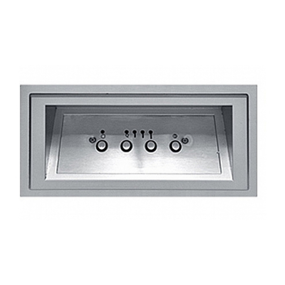
OPERATING INSTRUCTIONS This KOBE hood is equipped with four electronic controls with a 10-second standby startup & 30-second delay shutoff, two powerful centrifugal turbine impellers with baffle filters, and bright 12-volt 20-watt halogen lights. The four electronic controls are Light Control, Speed Control A, Speed Control B and the Power Control (On/Off). -
Page 21: Maintenance
MAINTENANCE For optimal performance, clean the range hood surface and baffles regularly. To Clean Hood Surface CAUTION: NEVER USE ABRASIVE CLEANERS, PADS, OR CLOTHS. *** Regular care will help preserve its fine appearance. 1. Use only mild soap or detergent solutions. Dry surfaces using soft cloth. 2. - Page 22 To Replace Light Bulb CAUTION: HALOGEN LIGHT UNIT MAY BE HOT! WAIT UNTIL UNIT IS COOL. NOTE: DO NOT TOUCH HALOGEN LIGHT WITH BARE HANDS, WHICH MIGHT CAUSE OVER HEAT AND SHORTEN THE LIFT OF LIGHT BULBS. 1. Make sure all controls are off, and range hood is unplugged. 2.
-
Page 23: Specifications
42” - 12V 20W x 3 48” - 12V 20W x 3 (CH7930SQB) 29-3/4” x 22” x 9-1/8” (CH7936SQB) 35-3/4” x 22” x 9-1/8” (CH7942SQB) 41-3/4” x 22” x 9-1/8” (CH7948SQB) 47-3/4” x 22” x 9-1/8” 1) 30" Stainless Steel Back Panel (SSP30) 30" x 1/10" x 32"... -
Page 24: Measurements & Diagrams
MEASUREMENTS & DIAGRAMS ***All inch measurements are converted from millimeters. Inch measurements are estimated. ***All measurements in ( ) are millimeters. - FOR UNDER THE CABINET - 30" = Knockout Holes “A” 36", 42”, 48” = Knockout Holes “A” & “B” - FOR WALL MOUNT (WITH OPTIONAL DUCT COVER) -... - Page 25 ***Hood-Mounting Bracket ***Duct Cover-Mounting Bracket...
-
Page 26: Parts List
PARTS LIST MODEL NO.: CH7930SQB CH7936SQB CH7942SQB CH7948SQB DESCRIPTION Multi Duct Exhaust Vent Cover (Top) Vent Cover (Rear) Vent Cover Frame Hood Casing Halogen Light (12V 20W Max.) Control Unit Control Board Control Panel Support Transformer Support Transformer (Motor) Air Chamber... - Page 27 MODEL NO.: CH7930SQB CH7936SQB...
- Page 28 MODEL NO.: CH7942SQB CH7948SQB...
-
Page 29: Circuit Diagram
CIRCUIT DIAGRAM MODEL NO.: CH7930SQB CH7936SQB... - Page 30 MODEL NO.: CH7942SQB CH7948SQB...
-
Page 31: Trouble Shooting
TROUBLE SHOOTING Issue Possible Cause After Installation, The power is not on. both motors and lights are not The wire connection is not secure. working. The control panel and processor board wiring are disconnected. The motor transformer is defective. The control panel and processor board is defective. -
Page 32: Disclaimer
DISCLAIMER 1. CAREFULLY INSPECT ALL ITEMS FOR DAMAGES BEFORE ACCEPTING DELIVERY. NOTE ANY DAMAGES ON THE FREIGHT BILL OR EXPRESS RECEIPT. REQUEST NAME AND SIGNATURE OF THE CARRIER’S AGENT AND KEEP COPY TO SUPPORT YOUR CLAIM. Upon acceptance of items, owner assumes responsibility for its safe arrival. Report damages to the carrier and file a claim immediately. -
Page 33: Warranty
WARRANTY KOBE Range Hoods, warrants all products manufactured or supplied by it to be free from defects in workmanship and materials. Its obligations pursuant to this warranty are limited to a period of two years from the date of purchase and to the repair or replacement at its option and subject to the terms and conditions stated below, of any component part, which its examination shall disclose to be so defective. -
Page 34: Consequential Damage
Some states do not allow limitations on the duration of implied warranties. This warranty gives you specific legal rights; you may have other rights, which vary from state to state. For service contact: KOBE Range Hoods 11775 Clark Street Arcadia, CA 91006 U.S.A. -
Page 35: Product Registration
KOBE Range Hoods Agent or KOBE Range Hoods as applicable. Keep proof of purchase (original invoice) handy for inspection. - Page 36 [FRENCH] - LIRE ET CONSERVER CES INSTRUCTIONS - TABLE DES MATIÈRES MESURES DE SÉCURITÉ IMPORTANTES ... 35 CONTENU DE LA BOÎTE... 37 INSTALLATION... 37 MODE D'EMPLOI ... 51 ENTRETIEN- NETTOYAGE... 52 SPÉCIFICATIONS... 54 MESURES et DIAGRAMMES ... 55 LISTE DES PIÈCES ... 57 DIAGRAMME DES CIRCUITS ...
-
Page 37: Mesures De Sécurité Importantes
MESURES DE SÉCURITÉ IMPORTANTES - SVP LIRE CETTE SECTION ATTENTIVEMENT AVANT L'INSTALLATION - AVERTISSEMENT L'installation et le câblage électrique doivent être effectués par des techniciens qualifiés et en conformité avec tous les codes et toutes les normes qui s'appliquent même pour les constructions ignifugées. - Page 38 Que faire en cas d'un incendie de graisse sur la cuisinière • ÉTOUFFER LES FLAMMES à l'aide d'un couvercle hermétique, une plaque à biscuits ou un plateau métallique, puis fermer le rond ou le brûleur. GARDER LES MATÉRIAUX INFLAMMABLES OU COMBUSTIBLES LOIN DES FLAMMES. Si les flammes ne s'éteignent pas immédiatement, ÉVACUER LA ZONE ET APPELER LE SERVICE D'INCENDIE ou le 911.
-
Page 39: Contenu De La Boîte
(vendue séparément) {H} Couvre conduit – 1 Ensemble de vis – 1 {J} Support de fixation du couvre conduit – 1 {K} Support de fixation – hotte – 1 – 2 OU COMMUNIQUER AVEC KOBE RANGE HOODS AU (626) 775-8880. -
Page 40: Installation
INSTALLATION VEUILLEZ LIRE ENTIÈREMENT LES INSTRUCTIONS AVANT DE PROCÉDER Calcul avant Installation Calculer la longueur de l'installation avant d'installer la hotte. (Toutes les mesures sont données en pouces). - HOTTE INSTALLÉE SOUS UNE ARMOIRE - TABLE 1 (vue de côté) A = hauteur du plancher au plafond B = hauteur du plancher jusqu’au comptoir/ à... -
Page 41: Installations
AVERTISSEMENT LES HOTTES COMPORTENT DES REBORDS TRÈS AFFILÉS; NOUS RECOMANDONS LE PORT DE GANTS PROTECTEURS LORS DE L’INSTALLATION, LE NETTOYAGE ET L’ENTRETIEN. MISE EN GARDE : SOYEZ PRUDENT EN EMPLOYANT UN TOURNEVIS ÉLECTRIQUE, CELA POURRAIT ENDOMMAGER LA HOTTE. INSTALLATIONS SOUS UNE AMOIRE Conduit Supérieur ……………………………………………………………………... - Page 42 INSTALLATION SOUS UNE ARMOIRE - CONDUIT SUPÉRIEUR Préparation avant l’installation NOTE : AFIN D’ÉVITER QUE VOTRE HOTTE NE SUBISSE DES DOMMAGES, ASSUREZ-VOUS QUE L’OUVERTURE N’EST PAS BLOQUÉE ET EMPÊCHER QUE DES DÉBRIS NE PENÈTRE DANS L’OUVERTURE DES CONDUITS. Planifier l'emplacement du conduit d’aération qui cheminera de la hotte vers l'extérieur. (Voir Photo 1) Un parcours droit, court et dirigé...
- Page 43 Installation de la hotte AVERTISSEMENT: S'il faut déplacer une cuisinière électrique pour installer la hotte, couper d'abord l'alimentation électrique à cette cuisinière par le tableau de distribution principal. COUPER LE GAZ AVANT DE DÉPLACER UNE CUISINIÈRE À GAZ. 1. Perforer les trous de décochage sur la hotte tel qu’indiqué à la Photo 4. 2.
- Page 44 INSTALLATION SOUS UNE ARMOIRE - CONDUIT ARRIÈRE Préparation avant installation NOTE: AFIN D’ÉVITER QUE VOTRE HOTTE NE SUBISSE DES DOMMAGES, ASSUREZ-VOUS QUE L’OUVERTURE N’EST PAS BLOQUÉE ET EMPÊCHER QUE DES DÉBRIS NE PENÈTRE DANS L’OUVERTURE DES CONDUITS. Planifier l'emplacement du conduit d’aération qui cheminera de la hotte vers l'extérieur. (Voir Photo 6) Un parcours droit, court et dirigé...
- Page 45 AVERTISSEMENT: S'il faut déplacer une cuisinière électrique pour installer la hotte, couper d'abord l'alimentation électrique à cette cuisinière par le tableau de distribution principal. COUPER LE GAZ AVANT DE DÉPLACER UNE CUISINIÈRE À GAZ. 1. Perforer les trous de décochage sur la hotte tel qu’indiqué à la Photo 10. 2.
- Page 46 INSTALLATION SOUS UN ÎLOT - CONDUIT SUPÉRIEUR *** Cette installation est possible uniquement avec l'achat d'un couvre-conduit en option. Préparation avant Installation NOTE: AFIN D’ÉVITER QUE VOTRE HOTTE NE SUBISSE DES DOMMAGES, ASSUREZ-VOUS QUE L’OUVERTURE N’EST PAS BLOQUÉE ET EMPÊCHER QUE DES DÉBRIS NE PENÈTRE DANS L’OUVERTURE DES CONDUITS.
- Page 47 Si nécessaire, fixer les deux fixations (fournis) en caoutchouc en compagnie des deux vis (4x8 mm) (fournies) à l’arrière de la hotte. Fixer le support de montage au dos de la hotte avec l’aide des neuf (3/16po x 3/8po) vis (fournies) tel qu’indiqué...
- Page 48 Installation avec couvre- conduits 3. Repérer la position de la fixation pour couvre conduit. Utiliser comme référence l’indication E de la Table 2 et le mesures à Page 55-56. Attacher de façon sécuritaire la fixation pour couvre conduit à l’aide de deux vis (non fournies). Référez-vous à la Photo 18. NOTE : la doublure du couvre conduit masquera la fixation.
- Page 49 INSTALLATION SOUS UN ÎLOT - CONDUIT ARRIÈRE *** Cette installation est possible uniquement avec l'achat d'un couvre-conduit en option. Préparation avant Installation NOTE: AFIN D’ÉVITER QUE VOTRE HOTTE NE SUBISSE DES DOMMAGES, ASSUREZ-VOUS QUE L’OUVERTURE N’EST PAS BLOQUÉE ET EMPÊCHER QUE DES DÉBRIS NE PENÈTRE DANS L’OUVERTURE DES CONDUITS.
- Page 50 Si nécessaire, fixer les deux fixations (fournis) en caoutchouc en compagnie des deux vis (4x8 mm) (fournies) à l’arrière de la hotte. Fixer le support de montage au dos de la hotte avec l’aide des neuf (3/16po x 3/8po) vis (fournies) tel qu’indiqué...
- Page 51 Installation avec couvre- conduit 4. Repérer la position de la fixation pour couvre conduit. Utiliser comme référence l’indication E de la Table deux (2) et le mesures à Page 55-56. Attacher de façon sécuritaire la fixation pour couvre conduit à l’aide de deux vis (non fournies). Référez-vous à la Photo 27. NOTE : la doublure du couvre conduit masquera la fixation.
-
Page 52: Avertissement De Sécurité
Connexion à l'alimentation d'énergie AVERTISSEMENT DE SÉCURITÉ POUR RÉDUIRE LE RISQUE D’INCENDIE OU D’ÉLECTROCUTION L’APPAREIL DOIT ÊTRE CORRECTEMENT MIS A LA TERRE. LES TRAVAUX D’INSTALLATION ET DE CÂBLAGE ÉLECTRIQUE DOIVENT ÊTRE FAITS PAR UN ÉLECTRICIEN QUALIFIÉ CONFORMÉMENT AUX CODES NATIONAUX ET LOCAUX ÉLECTRIQUES APPLICABLES. AVANT DE CONNECTER CET APPAREIL : ÉTEIGNEZ L’ALIMENTATION À... -
Page 53: Mode D'emploi
MODE D'EMPLOI Cette hotte de cuisinière KOBE possède quatre commandes électroniques munies d'un démarrage avec garde de 10 secondes et d'un dispositif d’arrêt à retardement de 30 secondes, deux puissants ventilateurs avec filtres déflecteurs et lampes halogènes 12 volts, 20 watts. Il existe quatre commandes électroniques: la commande des lampes «... -
Page 54: Entretien- Nettoyage
ENTRETIEN- NETTOYAGE Pour favoriser un rendement optimal, nettoyer régulièrement les surfaces de la hotte et les filtres déflecteurs. Nettoyage Des Surfaces De La Hotte AVERTISSEMENT : *** Un entretien fréquent aidera à conserver une belle apparence à la hotte. 1. Utiliser seulement du savon doux ou du détergent. Sécher les surfaces avec un chiffon doux. 2. - Page 55 Remplacement d'une ampoule AVERTISSEMENT : 1. S'assurer que toutes les commandes sont en mode ARRÊT et que la hotte de cuisinière est débranchée. 2. Glisser le tournevis à tête plate dans l'espace entre la plaque de verre et le boîtier de la lampe.
-
Page 56: Spécifications
48 po - 3 ampoules 12 V, 20 W (CH7930SQB) – 29-3/4 x 22 x 9-1/8 po (CH7936SQB) – 35-3/4 x 22 x 9-1/8 po (CH7942SQB) – 41-3/4 x 22 x 9-1/8 po (CH7948SQB) – 47-3/4 x 22 x 9-1/8 po 1) N de modèle SSP30... -
Page 57: Mesures Et Diagrammes
MESURES et DIAGRAMMES *** Toutes les mesures de pouce sont converties à partir de millimètres. Les mesures en pouces sont estimées. *** Toutes les mesures entre parenthèses ( ) sont des millimètres. - SOUS LE CABINET- 30po= Trous de montage perçage " A " 36po, 42po, 48po = Trous de montage "A et B "... - Page 58 *** Support de fixation – hotte *** Support de fixation – couvre-conduit...
-
Page 59: Liste Des Pièces
LISTE DES PIÈCES de modèles: CH7930SQB CH7936SQB CH7942SQB CH7948SQB DESCRIPTION Adaptateur de sortie multi conduit Plaque de sortie verticale Vis de plaque pour sortie verticale Adaptateur rectangulaire sortie arrière Caisson supérieur de la hotte Lumières halogènes (12V, 20W max.) Boîtier de contrôle Tableau de commandes (contrôle) - Page 60 CH7930SQB CH7936SQB...
- Page 61 de modèles CH7942SQB CH7948SQB...
-
Page 62: Diagramme Des Circuits
DIAGRAMME DES CIRCUITS de modèles CH7930SQB CH7936SQB... - Page 63 de modèles CH7942SQB CH7948SQB...
-
Page 64: Trouble Shooting
TROUBLE SHOOTING Problème Cause probable Après Pas d’alimentation électrique. Assurez- l’installation, vous que le disjoncteur et que les deux l’alimentation électrique moteurs et soient en marche. les lumières ne Le câblage n’est pas bien installé. fonctionnent Le câblage du panneau de commande et pas. -
Page 65: Avis De Non-Responsabilité
AVIS DE NON-RESPONSABILITÉ INSPECTER ATTENTIVEMENT TOUS LES ARTICLES POUR DÉCELER TOUT DOMMAGE, S'IL Y A LIEU, AVANT D'ACCEPTER LA LIVRAISON. NOTER TOUT DOMMAGE SUR LA FACTURE DE TRANSPORT OU LE CONNAISSEMENT. EXIGER LE NOM ET LA SIGNATURE DE L'EMPLOYÉ DU TRANSPORTEUR ET CONSERVER UNE COPIE COMME PIÈCE JUSTIFICATIVE DE LA RÉCLAMATION. -
Page 66: Garantie
GARANTIE Tous les produits fabriqués ou fournis par KOBE Range Hoods sont garantis contre tout défaut de fabrication et de matière première. Les obligations du fabricant dans le cadre de la présente garantie sont limitées à une période de deux (2) ans à partir de la date d'achat et à la réparation ou au remplacement, à... - Page 67 à l'extérieur du territoire de ventes principal du détaillant ou du territoire de service de l'agent autorisé de KOBE Range Hoods le plus près, selon le cas, de tous les frais de déplacement et de tous les frais de transport de la hotte ou de pièces de celle-ci jusqu'au détaillant ou au technicien de service (aller-retour).
-
Page 68: Enregistrement Du Produit
(ou, à notre discrétion, l'appareil pourra être remplacé), sans frais, par un agent autorisé de KOBE Range Hoods. ou par KOBE Range Hoods. selon le cas. Conservez votre preuve d'achat (ou facture d'origine) pour inspection. - Page 69 [SPANISH] - LEA Y CONSERVE ESTAS INSTRUCCIONES - ĺNDICE INSTRUCCIONES IMPORTANTES DE SEGURIDAD ... 68 COMPONENTES DEL PAQUETE... 70 INSTALACIÓN... 71 INSTRUCCIONES DE OPERACIÓN ... 84 MANTENIMIENTO ... 85 ESPECIFICACIONES ... 87 MEDIDAS Y DIAGRAMAS ... 88 LISTADO DE PIEZAS ... 90 DIAGRAMA DE CIRCUITO ...
-
Page 70: Instrucciones Importantes De Seguridad
KOBE RANGE HOODS anulará la garantía automáticamente. KOBE RANGE HOODS no se hará responsable por cualquier daño a la propiedad personal o inmobiliario ni por las lesiones físicas que se hayan causado ya sea directa o indirectamente por la campana de extracción. - Page 71 Qué Hacer en Caso de Un Incendio Causado por la Grasa Acumulada en las Hornillas de la Estufa • SOFOQUE LAS LLAMAS con una tapadera, una bandeja para hornear galletas o una bandeja de metal que quede bien ajustada y luego apague la hornilla. MANTENGA TODO EL MATERIAL INFLAMABLE O COMBUSTIBLE LEJOS DE LAS LLAMAS.
-
Page 72: Componentes Del Paquete
{H} Cubierta de Conductos - 1 {I} Paquete de Tornillos - 1 {J} Soporte de Montaje de la Cubierta de Conductos -1 {K} Soporte de Montaje de la Campana - 1 O CONT ACTE A KOBE RANGE HOODS AL (626) 775-8880. -
Page 73: Instalación
INSTALACIÓN POR FAVOR, LEA LAS INSTRUCCIONES COMPLETAMENTE ANTES DE CONTINUAR Cálculo antes de la Instalación Para realizar el cálculo para la instalación, por favor consulte la TABLA 1. (Todos los cálculos están hechos en pulgadas). - PARA INSTALACIÓN DEBAJO DEL GABINETE - TABLA 1 A = Altura del Piso al Techo B = Altura del Piso a la Superficie del... -
Page 74: Advertencia De Seguridad
ADVERTENCIA DE SEGURIDAD LA CAMPANA PODRÍA TENER EXTREMOS SUMAMENTE FILOSOS; FAVOR DE UTILIZAR GUANTES PROTECTORES SI VA A RETIRAR CUALQUIER PIEZA PARA INSTALAR, LIMPIAR O DARLE SERVICIO. NOTA: TENGA MUCHO CUIDADO AL UTILIZAR UN DESTORNILLADOR ELÉCTRICO; PODRÍA CAUSAR DAÑOS A LA CAMPANA. ĺndice de Instalación DEBAJO DEL GABINETE Ventilación Superior…………………………..……………………………………... - Page 75 INSTALACIÓN DEBAJO DEL GABINETE – VENTILACIÓN SUPERIOR Preparación antes de la Instalación NOTA: PARA EVITAR CAUSAR DAÑOS A SU CAMPANA, EVITE QUE DESECHOS PENETREN EN LA RENDIJA DE VENTILACIÓN Decida la ubicación para colocar el conducto de ventilación de la campana hacia el exterior.
- Page 76 Instalación de la Campana PRECAUCIÓN: Si fuera necesario mover la estufa para instalar la campana, desconecte la electricidad en la caja eléctrica principal si es una estufa eléctrica. APAGUE EL GAS ANTES DE MOVER UNA ESTUFA DE GAS. 1. Abra los oficios preperforados en la campana como se muestra en la Figura 4. 2.
- Page 77 INSTALACIÓN DEBAJO DEL GABINETE – VENTILACIÓN POSTERIOR Preparación antes de la instalación NOTA: PARA EVITAR CAUSAR DAÑOS A SU CAMPANA, EVITE QUE DESECHOS PENETREN EN LA RENDIJA DE VENTILACIÓN. Decida la ubicación para colocar el conducto de ventilación de la campana hacia el exterior.
- Page 78 Instalación de la Campana PRECAUCIÓN: Si fuera necesario mover la estufa para instalar la campana, desconecte la electricidad en la caja eléctrica principal si fuera una estufa eléctrica. APAGUE EL GAS ANTES DE MOVER UNA ESTUFA DE GAS. 1. Abra los oficios preperforados en la campana como se muestra en la Figura 10. 2.
- Page 79 INSTALACIÓN INDEPENDIENTE – VENTILACIÓN SUPERIOR ***Esta instalación sólo aplica con la compra de una cubierta de conductos. Preparación antes de la Instalación NOTA: PARA EVITAR CAUSAR DAÑOS A SU CAMPANA, EVITE QUE DESECHOS PENETREN EN LA RENDIJA DE VENTILACIÓN Decida la ubicación para colocar el conducto de ventilación de la campana hacia el exterior.
- Page 80 Si fuera necesario, coloque dos bases de goma (incluidas) con dos tornillos (4x8 mm) (incluidos) en la parte posterior de la campana. Coloque el soporte de montaje de la campana en la parte posterior de la misma con nueve tornillos (3/16" x 3/8") (incluidos) como se muestra en la Figura 16. Instalación de la Campana PRECAUCIÓN: Si fuera necesario mover la estufa para instalar la campana, desconecte la electricidad en la caja eléctrica principal, si es una estufa eléctrica.
- Page 81 Instalación de la Cubierta de Conductos 3. Marque la posición del soporte de montaje de la cubierta de conductos. Utilice la referencia E de la Tabla 2 y las medidas en las Paginas 88-89. Coloque y fije el soporte de montaje de la cubierta de conductos con dos tornillos (no incluidos). Consulte la Figura 18.
- Page 82 INSTALACIÓN INDEPENDIENTE – VENTILACIÓN POSTERIOR ***Esta instalación sólo aplica con la compra de una cubierta de conductos. Preparación antes de la Instalación NOTA: PARA EVITAR CAUSAR DAÑOS A SU CAMPANA, EVITE QUE DESECHOS PENETREN EN LA RENDIJA DE VENTILACIÓN Decida la ubicación para colocar el conducto de ventilación de la campana hacia el exterior.
- Page 83 Si fuera necesario, coloque dos bases de goma (incluidas) con dos tornillos de (4x8 mm) (incluidos) a la parte posterior de la campana. Coloque el soporte de montaje de la campana a la parte posterior de la misma con nueve tornillos de (3/16"...
- Page 84 Instalación de la Cubierta de Conductos 4. Marque la posición del soporte de montaje de la cubierta de conductos. Utilice la referencia E de la Tabla 2. Coloque y asegure el soporte de montaje de la cubierta de conductos con dos tornillos (no incluidos).
- Page 85 Cableado Hacia la Fuente de Alimentación ADVERTENCIA DE SEGURIDAD RIESGO DE ELECTROCUCIÓN. ESTA CAMPANA DE EXTRACCIÓN DEBE TENER UNA CONEXIÓN A TIERRA ADECUADA. ASEGÚRESE QUE ESTO SEA REALIZADO POR UN ELECTRICISTA ESPECIALIZADO ELÉCTRICOS APLICABLES NACIONALES Y LOCALES. ANTES DE CONECTAR LOS CABLES, DESCONECTE EL SUMINISTRO ELÉCTRICO EN EL PANEL DE SERVICIO Y CIERRE EL PANEL DE SERVICIO PARA PREVENIR QUE LA UNIDAD SE ENCIENDA ACCIDENTALMENTE.
-
Page 86: Instrucciones De Operación
INSTRUCCIONES DE OPERACIÓN Esta campana KOBE está equipada con cuatro controles electrónicos con un encendido en espera de 10 segundos y una desactivación luego de 30 segundos de retraso, dos poderosos impulsores de turbina centrifuga con pantallas de seguridad, focos brillantes de halógeno de 12-voltios 20-vatios. -
Page 87: Mantenimiento
MANTENIMIENTO Para funcionamiento deflectores/separadores/filtros/conductos de aceite/recipientes para aceite con regularidad. Limpieza de la Superficie de la Campana PRECAUCIÓN: NUNCA ABRASIVOS. NO UTILICE TOALLAS DE PAPEL SOBRE EL ACERO INOXIDABLE. ***El cuidado regular ayudará a preservar la apariencia de la campana. 1. - Page 88 Para Reemplazar el Foco PRECAUCIÓN: ¡LA UNIDAD DE LA LÁMPARA DE HALÓGENO PODRÍA ESTAR CALIENTE! ESPERE HASTA QUE SE ENFRÍE NOTA: NO TOQUE LA LÁMPARA DE HALÓGENO CON LAS MANOS DESPROTEGIDAS, PUES PODRÍA CAUSAR SOBRECALENTAMIENTO Y REDUCIR EL TIEMPO DE VIDA DE LOS FOCOS. 1.
-
Page 89: Especificaciones
42” - 12V 20W x 3 48” - 12V 20W x 3 (CH7930SQB) 29-3/4” x 22” x 9-1/8” (CH7936SQB) 35-3/4” x 22” x 9-1/8” (CH7942SQB) 41-3/4” x 22” x 9-/18” (CH7948SQB) 47-3/4” x 22” x 9-1/8” 1) Panel Posterior de Acero Inoxidable de 30"... -
Page 90: Medidas Y Diagramas
MEDIDAS Y DIAGRAM AS ***Todas las medidas en pulgadas han sido convertidas de milímetros. Las medidas en pulgadas son medidas aproximadas. ***Todas las medidas ( ) están en milímetros. - PARA DEBAJO DEL GABINETE - 30" = Agujeros preperforados “A” 36", 42”, 48”... - Page 91 ***Soporte de Montaje de la Campana ***Soporte de Montaje de la Cubierta de Conductos...
-
Page 92: Listado De Piezas
LISTADO DE PIEZAS MODEL NO.: CH7930SQB CH7936SQB CH7942SQB CH7948SQB DESCRIPTION Escape de Multi Conductos Cubierta de Ventilación (Superior) Cubierta de Ventilación (Posterior) Marco de la Cubierta de Ventilación Carcasa de la Campana Lámpara de Halógeno (12Vatios 20Watts Max.) Unidad de Control... - Page 93 MODELO NO.: CH7930SQB CH7936SQB...
- Page 94 MODELO NO.: CH7942SQB CH7948SQB...
-
Page 95: Diagrama De Circuito
DIAGRAMA DE CIRCUITO MODELO NO.: CH7930SQB CH7936SQB... - Page 96 MODELO NO.: CH7942SQB CH7948SQB...
-
Page 97: Instrucciones Importantes De Seguridad
INSTRUCCIONES IMPORTANTES DE SEGURIDAD Problema Posible Causa Después de la No está encendido. Instalación, ninguno de los motores ni las luces están La conexión de cables no está bien funcionando. sujeta. El cableado del panel de control y la placa de procesador está... -
Page 98: Cláusula De Exención
CLÁUSULA DE EXENCIÓN 1. INSPECCIONE CUIDADOSAMENTE TODOS LOS ARTÍCULOS VERIFICANDO QUE NO EXISTAN DAÑOS ANTES DE ACEPTAR LA ENTREGA. ANOTE CUALQUIER DAÑO EN LA FACTURA DE TRANSPORTE O EN EL RECIBO. PIDA EL NOMBRE Y FIRMA DEL AGENTE DE TRANSPORTE Y CONSERVE UNA COPIA PARA RESPALDAR SU RECLAMO. Al momento de aceptar los artículos, el propietario asume la responsabilidad de que lleguen de manera segura. -
Page 99: Garantía
(o reemplazada a nuestra discreción) sin costo alguno por parte de un Agente autorizado de KOBE Range Hoods o KOBE Range Hoods según corresponda. Tenga a la mano un comprobante de compra (o la factura original) para su verificación. - Page 100 Agente autorizado de KOBE Range Hoods más cercano según corresponda, así como de cualquier gasto de viaje y cualquier costo de transporte de la campana de extracción y piezas desde y hacia el concesionario y Agente de Servicio.
-
Page 101: Registro Del Producto
Agente autorizado de KOBE Range Hoods o KOBE Range Hoods según corresponda. Tenga a la mano un comprobante de compra (factura original) para su verificación. - Page 102 Utilizar una campana KOBE en el extranjero será a su propio riesgo y anulará la garantía. Information subject to change without notice. VER.091208 KOBE Range Hoods 11775 Clark Street Arcadia, CA 91006 USA http://www.KOBERangeHoods.com...
Need help?
Do you have a question about the CH7936SQB and is the answer not in the manual?
Questions and answers