
Subscribe to Our Youtube Channel
Related Manuals for INVENTOR INV-Pdm224W/NaB-M


Summary of Contents for INVENTOR INV-Pdm224W/NaB-M
- Page 1 I NV E NT OR I NV V R F S Y S T E MS D . C . I NV E R T E R MU L T I V R F I NV - P d m S e r v i c e Ma n u a l S e r v i c e Ma n u a l S e r v i c e Ma n u a l...
-
Page 2: Table Of Contents
CONTENTS PRODUCT ............................. 2 1 MODELS LIST ..........................2 1.1 Outdoor Unit ..........................2 1.2 Indoor Unit ..........................4 2 NOMENCLATURE ........................... 9 2.1 Nomenclature of Outdoor Unit ....................9 2.2 Nomenclature of Indoor Unit ....................9 3 FUNCTION ............................10 4 PRODUCT DATA .......................... - Page 3 8 INSTALLATION OF CONDENSATE PIPE ................157 8.1 Material Quality Requirements for Condensate Pipe ............157 8.2 Key Points for Condensate Pipe Installation ................. 157 8.3 Installation of Drainage Pipe for Different Types of Indoor Unit ......... 160 8.4 Test for Condensate Pipe ....................... 164 8.5 Requirements of Heat preservation ..................
- Page 4 INVENTOR COMMERCIAL AIR CONDITION MODULAR D.C. INVERTER MULTI PRODUCT...
-
Page 5: Product
MODULAR D.C. INVERTER MULTI VRF PRODUCT PRODUCT 1 MODELS LIST 1.1 Outdoor Unit Capacity Power Units Series Model Ref. Appearance Cooling Heating Supply (Btu/h) (Btu/h) INV-Pdm224W/NaB-M 76429 85300 380-415V R410A 3N~50Hz INV-Pdm280W/NaB-M 95536 107478 INV-Pdm335W/NaB-M 114302 127950 380-415V INV-Pdm400W/NaB-M 136480 153540... - Page 6 MODULAR D.C. INVERTER MULTI VRF PRODUCT Continue Capacity Units Power Model Ref. Appearance Cooling Heating Series Supply (Btu/h) (Btu/h) INV-Pdm1512W4/NaB-M 516918 576628 380-415V R410A INV-Pdm1570W4/NaB-M 528860 602218 MODULA 3N~50Hz R D.C. INV-Pdm1650W4/NaB-M 556156 619278 INVERTE R MULTI INV-Pdm1700W4/NaB-M 574922 639750 380-415V R410A INV-Pdm1750W4/NaB-M...
-
Page 7: Indoor Unit
MODULAR D.C. INVERTER MULTI VRF PRODUCT 1.2 Indoor Unit 1.2.1 Duct type Capacity Power Model Appearance Cooling Heating Supply (Btu/h) (Btu/h) INV-R22P/Na-K 8530 7507 INVL-R22P/Na-K INV-R25P/Na-K 10236 8530 INVL-R25P/Na-K INV-R28P/Na-K 10918 9554 INVL-R28P/Na-K INV-R32P/Na-K 12283 10919 INVL-R32P/Na-K INV-R36P/Na-K 13648 12284 INVL-R36P/Na-K INV-R40P/Na-K 15354... - Page 8 MODULAR D.C. INVERTER MULTI VRF PRODUCT Capacity Power Model Appearance Cooling Heating Supply (Btu/h) (Btu/h) INV-R22P/NaB-K 8530 7507 INVL-R22P/NaB-K INV-R25P/NaB-K 10236 8530 INVL-R25P/NaB-K INV-R28P/NaB-K 10918 9554 INVL-R28P/NaB-K INV-R36P/NaB-K 13648 12284 INVL-R36P/NaB-K INV-R45P/NaB-K 17060 15355 INVL-R45P/NaB-K 220V R410A 50Hz INV-R56P/NaB-K 21496 19108 INVL-R56P/NaB-K INV-R71P/NaB-K...
- Page 9 MODULAR D.C. INVERTER MULTI VRF PRODUCT 1.2.2 Cassette type Capacity Power Model Appearance Cooling Heating Supply (Btu/h) (Btu/h) INV-R28T/Na-K 10900 9550 INVL-R28T/Na-K INV-R36T/Na-K 13650 12280 INVL-R36T/Na-K INV-R45T/Na-K 17060 15360 INVL-R45T/Na-K INV-R50T/Na-K 19790 17060 INVL-R50T/Na-K 220V R410A 50Hz INV-R56T/Na-K 21500 19100 INVL-R56T/Na-K INV-R71T/Na-K 27300...
- Page 10 MODULAR D.C. INVERTER MULTI VRF PRODUCT 1.2.3 Wall mounted type Capacity Model Appearance Cooling Heating (Btu/h) (Btu/h) INV-R22G/NaB-K 8530 7507 INVL-R22G/NaB-K INV-R28G/NaB-K 10919 9554 INVL-R28G/NaB-K INV-R36G/NaB-K 13649 12284 INVL-R36G/NaB-K INV-R45G/NaB-K 17061 15355 INVL-R45G/NaB-K INV-R50G/NaB-K 19790 17061 INVL-R50G/NaB-K INV-R56G/NaB-K 21496 19108 INVL-R56G/NaB-K INV-R22G/NaC-K 8530...
- Page 11 MODULAR D.C. INVERTER MULTI VRF PRODUCT 1.2.4 Floor ceiling type Capacity Power Model Appearance Cooling Heating Supply (Btu/h) (Btu/h) INV-R28Zd/Na-K 10919 9554 INVL-R28Zd/Na-K INV-R36Zd/Na-K 13649 12284 INVL-R36Zd/Na-K INV-R50Zd/Na-K 19790 17061 INVL-R50Zd/Na-K INV-R71Zd/Na-K 27297 220V 24226 R410A 50Hz INVL-R71Zd/Na-K INV-R90Zd/Na-K 34121 30709 INVL-R90Zd/Na-K INV-R112Zd/Na-K...
-
Page 12: Nomenclature
K: 220-240V 50Hz Example: INV-R22G/NaB-K. A wall mounted indoor unit of INVENTOR, and the nominal cooling capacity is 2.2kw. It's the second generation product, and It could connect the outdoor unit with digital scroll, the power supply is 220V-240V, 50Hz. -
Page 13: Function
MODULAR D.C. INVERTER MULTI VRF PRODUCT 3 FUNCTION Auto Restart Fan Operation Mode LCD Remote Controller (Option) Auto Swing Function Ceiling Soiling Prevention Comfortable Program Dry Air Conditioning High Fan Speed Mode High Ceiling Application Two Select Thermo Sensor Hot Start Timer Selector Fresh Air Intake Directly from The Unit Drain Pump... -
Page 14: Product Data
MODULAR D.C. INVERTER MULTI VRF PRODUCT 4 PRODUCT DATA 4.1 Product data of outdoor Model INV-Pdm224W/NaB-M INV-Pdm280W/NaB-M Cooling capacity 22.4 28.0 Heating capacity 25.0 31.5 Sound Pressure Level dB(A) R410A charge amount Power Supply 380-415V 3N~50Hz 380-415V 3N~50Hz Cooling 5.52 7.52... - Page 15 MODULAR D.C. INVERTER MULTI VRF PRODUCT Model INV-Pdm335W/NaB-M INV-Pdm400W/NaB-M Cooling capacity 33.5 40.0 Heating capacity 37.5 45.0 Sound Pressure Level dB(A) R410A charge amount Power Supply 380-415V 3N~50Hz 380-415V 3N~50Hz Cooling 9.23 12.45 Rated power Heating 9.38 11.2 Cooling 16.50 22.25 Rated current...
- Page 16 MODULAR D.C. INVERTER MULTI VRF PRODUCT Model(Combined unit) INV-Pdm450W/NaB-M INV-Pdm504W/NaB-M INV-Pdm224W/NaB-M Model(Single unit) +INV-Pdm280W/NaB-M Cooling capacity 45.0 50.4 Heating capacity 50.0 56.5 Sound Pressure Level dB(A) R410A charge amount 12+13 Power Supply 380-415V 3N~50Hz 380-415V 3N~50Hz Cooling 14.32 5.52+7.52 Rated power Heating 13.90...
- Page 17 MODULAR D.C. INVERTER MULTI VRF PRODUCT Model (Combined unit) INV-Pdm560W2/NaB-M INV-Pdm615W2/NaB-M INV-Pdm280W/NaB-M INV-Pdm280W/NaB-M Model(Single unit) + INV-Pdm280W/NaB-M + INV-Pdm335W/NaB-M Cooling capacity 56.0 61.5 Heating capacity 63.0 69.0 Sound Pressure Level dB(A) R410A charge 13+13 13+15 amount Power Supply 380-415V 3N~50Hz 380-415V 3N~50Hz Cooling 7.52+7.52...
- Page 18 MODULAR D.C. INVERTER MULTI VRF PRODUCT Model (Combined unit) INV-Pdm670W2/NaB-M INV-Pdm730W2/NaB-M INV-Pdm280W/NaB-M INV-Pdm280W/NaB-M Model(Single unit) + INV-Pdm400W/NaB-M + INV-Pdm450W/NaB-M Cooling capacity 68.0 73.0 Heating capacity 76.5 81.5 Sound Pressure dB(A) Level R410A charge 13+16 13+17 amount Power Supply 380-415V 3N~50Hz 380-415V 3N~50Hz Cooling 7.52+12.45...
- Page 19 MODULAR D.C. INVERTER MULTI VRF PRODUCT Model (Combined unit) INV-Pdm785W2/NaB-M INV-Pdm850W2/NaB-M INV-Pdm335W/NaB-M INV-Pdm400W/NaB-M Model(Single unit) + INV-Pdm450W/NaB-M + INV-Pdm450W/NaB-M Cooling capacity 78.5 85.0 Heating capacity 87.5 95.0 Sound Pressure Level dB(A) R410A charge 15+16 16+17 amount Power Supply 380-415V 3N~50Hz 380-415V 3N~50Hz Cooling 9.23+14.32...
- Page 20 MODULAR D.C. INVERTER MULTI VRF PRODUCT Model (Combined unit) INV-Pdm900W2/NaB-M INV-Pdm950W3/NaB-M INV-Pdm280W/NaB-M INV-Pdm450W/NaB-M Model(Single unit) +INV-Pdm280W/NaB-M + INV-Pdm450W/NaB-M + INV-Pdm400W/NaB-M Cooling capacity 90.0 96.0 Heating capacity 100.0 108.0 dB(A Sound Pressure Level R410A charge 17+17 13+13+16 amount Power Supply 380-415V 3N~50Hz 380-415V 3N~50Hz Cooling 14.32+14.32...
- Page 21 MODULAR D.C. INVERTER MULTI VRF PRODUCT Model (Combined unit) INV-Pdm1008W3/NaB-M INV-Pdm1065W3/NaB-M INV-Pdm280W/NaB-M INV-Pdm280W/NaB-M Model(Single unit) +INV-Pdm280W/NaB-M +INV-Pdm335W/NaB-M + INV-Pdm450W/NaB-M + INV-Pdm450W/NaB-M Cooling capacity 101.0 106.5 Heating capacity 113.0 119.0 Sound Pressure Level dB(A) R410A charge 13+13+17 13+15+17 amount Power Supply 380-415V 3N~50Hz 380-415V 3N~50Hz Cooling...
- Page 22 MODULAR D.C. INVERTER MULTI VRF PRODUCT Model (Combined unit) INV-Pdm1130W3/NaB-M INV-Pdm1180W3/NaB-M INV-Pdm280W/NaB-M INV-Pdm280W/NaB-M + INV-Pdm400W/NaB-M + INV-Pdm450W/NaB-M Model(Single unit) + INV-Pdm450W/NaB-M + INV-Pdm450W/NaB-M Cooling capacity 113.0 118.0 Heating capacity 126.5 131.5 Sound Pressure Level dB(A) R410A charge amount 13+16+17 13+17+17 Power Supply 380-415V 3N~50Hz 380-415V 3N~50Hz...
- Page 23 MODULAR D.C. INVERTER MULTI VRF PRODUCT Model (Combined unit) INV-Pdm1235W3/NaB-M INV-Pdm1300W3/NaB-M INV-Pdm335W/NaB-M INV-Pdm400W/NaB-M Model(Single unit) + INV-Pdm450W/NaB-M + INV-Pdm450W/NaB-M + INV-Pdm450W/NaB-M + INV-Pdm450W/NaB-M Cooling capacity 123.5 130.0 Heating capacity 137.5 145.0 Sound Pressure Level dB(A) R410A charge 15+17+17 16+17+17 amount Power Supply 380-415V 3N~50Hz 380-415V 3N~50Hz...
- Page 24 MODULAR D.C. INVERTER MULTI VRF PRODUCT Model (Combined unit) INV-Pdm1350W3/NaB-M INV-Pdm1405W4/NaB-M INV-Pdm280W/NaB-M INV-Pdm450W/NaB-M + INV-Pdm280W/NaB-M Model(Single unit) + INV-Pdm450W/NaB-M + INV-Pdm400W/NaB-M + INV-Pdm450W/NaB-M + INV-Pdm450W/NaB-M Cooling capacity 135.0 141.0 Heating capacity 150.0 158.0 Sound Pressure Level dB(A) R410A charge 17+17+17 13+13+16+17 amount Power Supply...
- Page 25 MODULAR D.C. INVERTER MULTI VRF PRODUCT Model (Combined unit) INV(L)-Pdm1456W4/NaB-M INV(L)-Pdm1512W4/NaB-M INV(L)-Pdm280W/NaB-M INV(L)-Pdm280W/NaB-M + INV(L)-Pdm280W/NaB-M + INV(L)-Pdm335W/NaB-M Model(Single unit) + INV(L)-Pdm450W/NaB-M + INV(L)-Pdm450W/NaB-M + INV(L)-Pdm450W/NaB-M + INV(L)-Pdm450W/NaB-M Cooling capacity 146.0 151.5 Heating capacity 163.0 169.0 Sound Pressure Level dB(A) R410A charge amount 13+13+17+17 13+15+17+17 Power Supply...
- Page 26 MODULAR D.C. INVERTER MULTI VRF PRODUCT Model (Combined unit) INV-Pdm1570W4/NaB-M INV-Pdm1650W4/NaB-M INV-Pdm280W/NaB-M INV-Pdm280W/NaB-M + INV-Pdm400W/NaB-M + INV-Pdm450W/NaB-M Model(Single unit) + INV-Pdm450W/NaB-M + INV-Pdm450W/NaB-M + INV-Pdm450W/NaB-M + INV-Pdm450W/NaB-M Cooling capacity 155.0 163.0 Heating capacity 176.5 181.5 Sound Pressure Level dB(A) R410A charge amount 13+16+17+17 13+17+17+17 Power Supply...
- Page 27 MODULAR D.C. INVERTER MULTI VRF PRODUCT Model (Combined unit) INV-Pdm1700W4/NaB-M INV-Pdm1750W4/NaB-M INV-Pdm335W/NaB-M INV-Pdm400W/NaB-M + INV-Pdm450W/NaB-M + INV-Pdm450W/NaB-M Model(Single unit) + INV-Pdm450W/NaB-M + INV-Pdm450W/NaB-M + INV-Pdm450W/NaB-M + INV-Pdm450W/NaB-M Cooling capacity 168.5 175.0 Heating capacity 187.5 195.0 Sound Pressure Level dB(A) R410A charge amount 15+17+17+17 16+17+17+17 Power Supply...
- Page 28 MODULAR D.C. INVERTER MULTI VRF PRODUCT Model (Combined unit) INV(L)-Pdm1800W4/NaB-M INV-Pdm450W/NaB-M+ INV-Pdm450W/NaB-M Model(Single unit) + INV-Pdm450W/NaB-M+ INV-Pdm450W/NaB-M Cooling capacity 180.0 Heating capacity 200.0 Sound Pressure Level dB(A) R410A charge amount 17+17+17+17 Power Supply 380-415V 3N~50Hz Cooling 14.32+14.32+14.32+14.32 Rated power Heating 13.90+13.90+13.90+13.90 Cooling 25.60+25.60+25.60+25.60...
-
Page 29: Product Data Of Indoor
MODULAR D.C. INVERTER MULTI VRF PRODUCT 4.2 Product data of indoor 4.2.1 Duct Type Model INV(L)-R22P/Na-K INV(L)-R25P/Na-K INV(L)-R28P/Na-K Cooling Capacity 7506 8530 9554 Heating Capacity 8530 10236 10918 m3/h Air Flow Rate Sound Pressure Level (H/L) dB(A) 37/33 37/33 39/35 External Static Pressure Power Supply 220-240V~50Hz... - Page 30 MODULAR D.C. INVERTER MULTI VRF PRODUCT Model INV(L)-R32P/Na-K INV(L)-R36P/Na-K INV(L)-R40P/Na-K Cooling Capacity 10919 12284 13649 Heating Capacity 12283 13648 15354 m3/h Air Flow Rate Sound Pressure Level (H/L) dB(A) 39/35 39/35 40/36 External Static Pressure Power Supply 220-240V~50Hz 220-240V~50Hz 220-240V~50Hz Output 0.02 0.02...
- Page 31 MODULAR D.C. INVERTER MULTI VRF PRODUCT Model INV(L)-R45P/Na-K INV(L)-R50P/Na-K INV(L)-R56P/Na-K Cooling Capacity 15355 17061 19108 Heating Capacity 17060 19790 21496 m3/h 1400 Air Flow Rate Sound Pressure Level (H/L) dB(A) 40/36 40/36 42/38 External Static Pressure Power Supply 220-240V~50Hz 220-240V~50Hz 220-240V~50Hz Output 0.07...
- Page 32 MODULAR D.C. INVERTER MULTI VRF PRODUCT Model INV(L)-R63P/Na-K INV(L)-R71P/Na-K INV(L)-R80P/Na-K Cooling Capacity 21496 24226 27297 Heating Capacity 23884 27296 30026 m3/h 1400 1400 1400 Air Flow Rate Sound Pressure Level (H/L) dB(A) 42/38 42/38 42/38 External Static Pressure Power Supply 220-240V~50Hz 220-240V~50Hz 220-240V~50Hz...
- Page 33 MODULAR D.C. INVERTER MULTI VRF PRODUCT Model INV(L)-R90P/Na-K INV(L)-R100P/Na-K INV(L)-R112P/Na-K 10.0 11.2 Cooling Capacity 30709 34121 38216 10.0 11.0 12.5 Heating Capacity 34120 37532 42650 m3/h 2000 2000 2000 Air Flow Rate 1177 1177 1177 Sound Pressure Level (H/L) dB(A) 44/40 44/40 44/40...
- Page 34 MODULAR D.C. INVERTER MULTI VRF PRODUCT Model INV(L)-R125P/Na-K INV(L)-R140P/Na-K INV(L)-R224P/Na-K 12.5 14.0 22.4 Cooling Capacity 42652 47770 76432 13.5 15.0 25.0 Heating Capacity 46060 51180 85304 m3/h 2000 2000 4000 Air Flow Rate 1177 1177 2354 Sound Pressure Level (H/L) dB(A) 44/40 45/41...
- Page 35 MODULAR D.C. INVERTER MULTI VRF PRODUCT Model INV(L)-R280P/Na-K INV(L)-R22P/NaB-K INV(L)-R25P/NaB-K 28.0 Cooling Capacity 95540 7507 8530 31.0 Heating Capacity 105780 8530 10236 m3/h 4800 Air Flow Rate 2825 Sound Pressure Level (H/L) dB(A) 57(H) 37/33 37/33 External Static Pressure 50/20 50/20 Power Supply 380V,3N~50Hz...
- Page 36 MODULAR D.C. INVERTER MULTI VRF PRODUCT Model INV(L)-R28P/NaB-K INV(L)-R36P/NaB-K INV(L)-R45P/NaB-K Cooling Capacity 9554 12284 15355 Heating Capacity 10918 13648 17060 m3/h Air Flow Rate Sound Pressure Level (H/L) dB(A) 39/35 39/35 40/36 External Static Pressure 50/20 50/20 50/20 Power Supply 220-240V~50Hz 220-240V~50Hz 220-240V~50Hz...
- Page 37 MODULAR D.C. INVERTER MULTI VRF PRODUCT Model INV(L)-R56P/NaB-K INV(L)-R71P/NaB-K INV(L)-R90P/NaB-K Cooling Capacity 19108 24226 30709 10.0 Heating Capacity 21496 27296 34120 m3/h 1400 1400 2000 Air Flow Rate 1177 Sound Pressure Level (H/L) dB(A) 42/38 42/38 44/40 External Static Pressure 60/30 60/30 80/40...
- Page 38 MODULAR D.C. INVERTER MULTI VRF PRODUCT Model INV(L)-R112P/NaB-K INV(L)-R140P/NaB-K 11.2 14.0 Cooling Capacity 38216 47770 12.5 15.0 Heating Capacity 42650 51180 m3/h 2000 2500 Air Flow Rate 1177 1471 Sound Pressure Level (H/L) dB(A) 44/40 45/41 External Static Pressure 80/40 100/50 Power Supply 220-240V~50Hz...
- Page 39 MODULAR D.C. INVERTER MULTI VRF PRODUCT 4.2.2Cassete Type Model INV(L)-R28T/Na-K INV(L)-R36T/Na-K INV(L)-R45T/Na-K Cooling Capacity 9550 12280 15360 Heating Capacity 10900 13650 17060 m3/h Air Flow Rate Sound Pressure Level (H/L) dB(A) 37/34 37/34 37/34 External Static Pressure Power Supply 220-240V~50Hz 220-240V~50Hz 220-240V~50Hz Output...
- Page 40 MODULAR D.C. INVERTER MULTI VRF PRODUCT Model INV(L)-R50T/Na-K INV(L)-R56T/Na-K INV(L)-R71T/Na-K Cooling Capacity 17060 19100 24230 Heating Capacity 19790 21500 27300 m3/h 1180 1180 Air Flow Rate Sound Pressure Level (H/L) dB(A) 37/34 39/35 39/35 External Static Pressure Power Supply 220-240V~50Hz 220-240V~50Hz 220-240V~50Hz Output...
- Page 41 MODULAR D.C. INVERTER MULTI VRF PRODUCT Model INV(L)-R90T/Na-K INV(L)-R112T/Na-K 11.2 Cooling Capacity 30700 38210 10.0 12.5 Heating Capacity 34120 42650 m3/h 1860 1860 Air Flow Rate 1095 1095 Sound Pressure Level (H/L) dB(A) 40/36 40/36 External Static Pressure Power Supply 220-240V~50Hz 220-240V~50Hz Output...
- Page 42 MODULAR D.C. INVERTER MULTI VRF PRODUCT 4.2.3Wall mounted Type Model INV(L)-R22G/NaB-K INV(L)-R28G/NaB-K INV(L)-R36G/NaB-K Cooling Capacity 7507 9554 12284 Heating Capacity 8530 10919 13649 m3/h Air Flow Rate Sound Pressure Level dB(A) 37/28 37/28 43/28 (H/L) External Static Pressure Power Supply 220-240V~50Hz 220-240V~50Hz 220-240V~50Hz...
- Page 43 MODULAR D.C. INVERTER MULTI VRF PRODUCT Model INV(L)-R45G/NaB-K INV(L)-R50G/NaB-K INV(L)-R56G/NaB-K Cooling Capacity 15355 17061 19108 Heating Capacity 17061 19790 21496 m3/h Air Flow Rate Sound Pressure Level (H/L) dB(A) 43/28 45/40 45/40 External Static Pressure Power Supply 220-240V~50Hz 220-240V~50Hz 220-240V~50Hz Output 0.022 0.02...
- Page 44 MODULAR D.C. INVERTER MULTI VRF PRODUCT Model INV(L)-R22G/NaC-K INV(L)-R28G/NaC-K INV(L)-R36G/NaC-K Cooling Capacity 7507 9554 12284 Heating Capacity 8530 10919 13649 m3/h Air Flow Rate Sound Pressure Level (H/L) dB(A) 37/28 37/28 43/28 External Static Pressure Power Supply 220-240V~50Hz 220-240V~50Hz 220-240V~50Hz Output 0.014 0.014...
- Page 45 MODULAR D.C. INVERTER MULTI VRF PRODUCT Model INV(L)-R45G/NaC-K INV(L)-R50G/Na-K INV(L)-R56G/Na-K Cooling Capacity 15355 17061 19108 Heating Capacity 17061 19790 21496 m3/h Air Flow Rate Sound Pressure Level (H/L) dB(A) 43/28 42/38 45/40 External Static Pressure Power Supply 220-240V~50Hz 220-240V~50Hz 220-240V~50Hz Output 0.022 0.02...
- Page 46 MODULAR D.C. INVERTER MULTI VRF PRODUCT Model INV(L)-R71G/Na-K INV(L)-R80G/Na-K Cooling Capacity 24226 27297 Heating Capacity 27297 30709 m3/h 1200 1200 Air Flow Rate Sound Pressure Level (H/L) dB(A) 49/42 49/42 External Static Pressure Power Supply 220-240V~50Hz 220-240V~50Hz Output 0.026 0.026 Fan Motor Running Current 0.29...
- Page 47 MODULAR D.C. INVERTER MULTI VRF PRODUCT 4.2.4Floor Ceiling Type Model INV(L)-R28Zd/Na-K INV(L)-R36Zd/Na-K INV(L)-R50Zd/Na-K Cooling Capacity 9554 12284 17061 Heating Capacity 10919 13649 19790 m3/h Air Flow Rate Sound Pressure Level (H/L) dB(A) 43/- 44/- 50/- External Static Pressure Power Supply 220-240V~50Hz 220-240V~50Hz 220-240V~50Hz...
- Page 48 MODULAR D.C. INVERTER MULTI VRF PRODUCT Model INV(L)-R71Zd/Na-K INV(L)-R90Zd/Na-K Cooling Capacity 24226 30709 10.0 Heating Capacity 27297 34121 m3/h 1170 2100 Air Flow Rate 1236 Sound Pressure Level (H/L) dB(A) 48/- 51/- External Static Pressure Power Supply 220-240V~50Hz 220-240V~50Hz Output 0.15 Fan Motor Running Current...
-
Page 49: Operation Range
MODULAR D.C. INVERTER MULTI VRF PRODUCT Model INV(L)-R112Zd/Na-K INV(L)-R125Zd/Na-K 11.2 12.5 Cooling Capacity 38216 42652 12.5 13.5 Heating Capacity 42652 46064 m3/h 2200 2300 Air Flow Rate 1295 1354 Sound Pressure Level (H/L) dB(A) 54/- 55/- External Static Pressure Power Supply 220-240V~50Hz 220-240V~50Hz Output... -
Page 50: Piping Diagram
MODULAR D.C. INVERTER MULTI VRF PRODUCT 5 PIPING DIAGRAM compressor High pressure sensor D.C.Inverter Scroll type compressor Gas by-pass value sub-assy:electromagnetic value Discharge temperature sensor Gas by-pass value sub-assy:capillary Gas equilibrium pipe condenser Oil equilibrium pipe Condenser inlet temperature sensor Oil separator Condenser middle temperature sensor Oil separator sub-assy:Filter... - Page 51 INVENTOR COMMERCIAL AIR CONDITION MODULAR D.C. INVERTER MULTI CONTROL...
-
Page 52: Control
MODULAR D.C. INVERTER MULTI VRF CONTROL CONTROL 1 CONTROL OF THE UNIT 1.1 Concept of Integral Control of the Unit 1.1.1 Unit Control Schematic Diagram Inverter drive control system 2-core communication 2-core cable (3-core pin header communication cable Adapt (3-core pin header Main control board of board outdoor unit... - Page 53 MODULAR D.C. INVERTER MULTI VRF CONTROL bypass valve and capillary solenoid valve. C 485 communication interface:indoor unit communication network and adaptor board CN1 shall be connected to the mainboard of indoor unit through 2-core (3-core pin header) communication cable; drive communication network and the mainboards CN11~CN14 of outdoor unit shall be connected to the drive board through 2-core (3-core pin header) communication cable.
-
Page 54: Operation Flow Chart Of The Unit
MODULAR D.C. INVERTER MULTI VRF CONTROL 1.2 Operation Flow Chart of the Unit 1.2.1 Operation Flow Chart of the Unit 接通电源 The unit is powered on 电子膨胀阀初始化 The electronic expansion valve is initialized Air flow, air direction 显示上次设定的风量、 运行灯点亮 The running indicator is bright. temperature that were set last 风向、温度设定。... - Page 55 MODULAR D.C. INVERTER MULTI VRF CONTROL ◆ Cooling running 制冷运转 Cooling running 无 导风板 Guide Louver 有 导风板摆动 Guide louver is swaying 风机:以设定风量运转 Fan: running at set air flow 正在防止再次 是 Is restart being 启动运转中? avoided? (3 minutes) (3分钟) 否 否...
- Page 56 MODULAR D.C. INVERTER MULTI VRF CONTROL ◆ Heating running 制热运行 Cooling running 无 导风板 Guide Louver 有 导风板摆动 Guide louver is swaying 除霜 是 Is defrost 运转中? running? 否 正在防止再次 Is restart being 是 启动运转中? avoided? (3 minutes) (3分钟) 否 否...
- Page 57 MODULAR D.C. INVERTER MULTI VRF CONTROL ◆ Drying running 除湿运转 Drying running 无 导风板 Guide Louver 有 导风板摆动 Guide louver is swaying 风机:低风速运行 Fan: running at low speed 正在防止再 是 Is restart being 次启动运转中? avoided? (3 minutes) (3分钟) 否 否 Temperature 温度调节?...
- Page 58 MODULAR D.C. INVERTER MULTI VRF CONTROL 1.2.2 Operation Flow Chart of Outdoor Unit 接通电源 The unit is powered on 电子膨胀阀:初始化 The electronic expansion valve: initialized 送风 Air supply Air supply or 送风或温度调节? temperature regulation? 温度调节 Temperature regulation 是 正在防止再次启动? Is restart being avoided? (3 minutes) (3分钟)...
- Page 59 MODULAR D.C. INVERTER MULTI VRF CONTROL ◆ Cooling Running 制冷运转 Cooling running 是 正在起动初始化? Is startup being initialized? 否 是 正在压缩机保护? Is compressor being protected? 否 四通阀: 关闭 四通阀: 关闭 四通阀: 关闭 4-way valve: stop 4-way valve: stop 4-way valve: stop 室外风机:制冷控制方式...
-
Page 60: Control Functions Of The Unit
MODULAR D.C. INVERTER MULTI VRF CONTROL 1.3 Control Functions of the Unit 1.3.1 Control Functions of Outdoor Unit Capacity d istribution of compressor Principle: after the total capacity is distributed to the single unit of various modules, inverter compressor and fixed frequency compressor shall be assigned by means of overflow method, i.e. - Page 61 MODULAR D.C. INVERTER MULTI VRF CONTROL If capacity demand asks inverter + fixed frequency 1 to start in the period, if target frequency of inverter compressor is lower than frequency of stop points, up-conversion is unnecessary. Target frequency 变频 Inverter 定频1 Fixed frequency 1 Fixed frequency 2...
- Page 62 MODULAR D.C. INVERTER MULTI VRF CONTROL 25%≤P<40% 40%≤P<60% 60%≤P<80% P≥80% Output capacity P<25% T≤0 0<T≤12 10Hz 10Hz 10Hz 15Hz 20Hz 23Hz 25Hz 12<T≤20 Max. 20<T≤35 28Hz 33Hz 38Hz 44Hz frequency Value Max. 36Hz 38Hz 41Hz 44Hz 35<T≤40 Value Max. T>40 Max.
- Page 63 MODULAR D.C. INVERTER MULTI VRF CONTROL 1.3.2 Control Function of Indoor Unit Contain: Cooling Operation Cooling According to the capacity demand of the running indoor unit, the outdoor unit decides the frequency under which the compressor runs. control of the outdoor unit, the indoor unit decides the openness of the electronic expansion valve. The electronic expansion valve is set once every 40 seconds.
- Page 64 MODULAR D.C. INVERTER MULTI VRF CONTROL Dehumidifying Operation When the unit operates under the dehumidifying mode, the indoor unit can only operates under the low air speed grade (regardless of the set air speed grade). Other actions are the same as that of the cooling operation. Please refer to the section of cooling operation.
- Page 65 MODULAR D.C. INVERTER MULTI VRF CONTROL the indoor fan motor stops before, the fan motor will start compulsory operation under high air speed grade for 8 seconds and then operates under set air speed. Operation of Preventing Cold Air When the indoor unit has capacity demand, the indoor fan motor will be compulsorily turned to close status and operate under the following conditions: If the evaporator temperature (t ) of the indoor unit reaches the threshold T...
- Page 66 MODULAR D.C. INVERTER MULTI VRF CONTROL Expansion Valve ON Expansion Valve OFF Indoor Ambient Temperature Indoor Set Temperature (Temperature At Air Intake) Temperature Adjustment Under Standard Conditions Expansion Valve ON Expansion Valve Indoor Ambient Temperature Indoor Set Temperature (Temperature At Air Intake) Temperature Adjustment With Temperature Compensation Anti-Frosting Control Under Cooling And Dehumidifying Modes To prevent the frosting...
- Page 67 MODULAR D.C. INVERTER MULTI VRF CONTROL When the wire controller or the remote controller sends the signal of stopping automatic swing, the indoor unit will stop automatic swing operation and the swing louvers will stop at the current location. ◆ Others When the indoor unit receives the signal of switching-off, detects the failure signals other than the auxiliary electrical heating protection signal, and detects the defrosting signal, the indoor unit, regardless of which state the swing louvers are in, will stop to return to the initial position after the indoor fan motor stops.
- Page 68 MODULAR D.C. INVERTER MULTI VRF CONTROL under the status of ambient temp. sensor failure, the signal of ambient temp. sensor failure is removed and the indoor unit resumes the original operating status. ◆ Evaporator Tube Temp. Sensor When it is detected that the evaporator tube temperature is continuously lower than -30℃ for 1 minute or is continuously higher than 100℃...
-
Page 69: Wireless Remote Controller
MODULAR D.C. INVERTER MULTI VRF CONTROL 2 WIRELESS REMOTE CONTROLLER NOTE! ● Make sure that there is no obstruction between the remote control and the signal receptor. ● The remote control signal can be received at the distance of up to about 10m. ●... -
Page 70: Operation Procedure
MODULAR D.C. INVERTER MULTI VRF CONTROL Liquid crystal displayer It shows all set contents. SWING SLEEP button Press the button to set SLEEP AUTOFAN OPER mode, and stop when repressed. AUTO When the sleep mode is in the cool and dry mode, the set temp. -
Page 71: How To Insert Batteries
MODULAR D.C. INVERTER MULTI VRF CONTROL How to insert batteries Two batteries (Two AAA dry-cell batteries) are used by the remote control 1. Remote the cover from the back of the remote control downward, take out the worn batteries and insert two new ones (Make sure the two poles are correct) 2. -
Page 72: Wired Remote Controller
MODULAR D.C. INVERTER MULTI VRF CONTROL 3 WIRED REMOTE CONTROLLER_ 3.1 Operation View Fig.4.1 Various Components of Wired Remote Controller Operating mode display (Cool, Dry, Fan, Heat) On/Off button Sleep mode display Timer button Environmental temp. display /Malfunction display Sleep button Fan control display (automatic, high, media, low) Swing display Set Temp. -
Page 73: Dimension
MODULAR D.C. INVERTER MULTI VRF CONTROL 3.2 Dimension Fig.4.3.1 Outlinr dimension of wireless remote controller Fig.4.3.2 Installation dimension of wireless remote controller 3.3 Installation Fig.4.4 Installation of wire remote controller Name Casing base, installed into the wall Controller Soleplate Screw M4X25 Controller Panel ●Notice for installation under the guidance of Fig.10 1. -
Page 74: Mini Centralized Controller
MODULAR D.C. INVERTER MULTI VRF CONTROL 4 MINI CENTRALIZED CONTROLLER 4.1 Function Region monitoring control and region wired control are the two main control functions for mini centralized controller (region controller). Region monitoring controller can monitor or control 16 indoor units of a group for inquiry and single or centralized control. -
Page 75: Operation View
MODULAR D.C. INVERTER MULTI VRF CONTROL 4.2 Operation View (Fig.4.2) Name Function A. Switch the control mode of inquiry/single/ central control. FUNC B. In central control status, give the central order by successively pressing FUNC (FUNCTION) button. MODE Set cooling/heating/fan/dry mode for indoor unit ▲... -
Page 76: Display View
MODULAR D.C. INVERTER MULTI VRF CONTROL 4.3 Display View (Fig.4.3) - Page 77 MODULAR D.C. INVERTER MULTI VRF CONTROL Display name Instruction to display Inquiry state, ―INQUIRY‖ is displayed. Single control state,‖SINGLE‖ is displayed. Control mode Centralized control state, ―CENTER‖ is displayed. Running mode Each indoor unit running mode is displayed. ―ERROR‖ is displayed during any malfunction to indoor or outdoor unit in a group. Error ―-...
-
Page 78: Connection Between Controller And Unit
MODULAR D.C. INVERTER MULTI VRF CONTROL 4.4 Connection Between Controller and Unit Insert the 4-core twisted pair line to wired controller, if which is with the indoor unit, into mini centralized controller (region controller) wiring terminal CN1 (or CN2), and then connect the other wiring terminal CN2 (or CN1) with the main board of indoor unit. -
Page 79: Centralized Controller
MODULAR D.C. INVERTER MULTI VRF CONTROL 5 CENTRALIZED CONTROLLER 5.1 Function Main characteristics of Centralized Controller: ◆ A set of Centralized Controller can control 64 communication modules and can connect to as much as 1024 indoor units. It can conduct individual control with any separated area or unified control. - Page 80 MODULAR D.C. INVERTER MULTI VRF CONTROL This central control has Sequence On function, that enable conduction to sequence control to communication modular in interval of 2 seconds, communication modular ALL ON controls Sequence On of indoor units (to lower impact to power network). This central control has Sequence Off function, that enable conduction of sequence control to communication modular in interval of 2 seconds, communication module ALL OFF...
-
Page 81: Display View
MODULAR D.C. INVERTER MULTI VRF CONTROL 5.3 Display View Sketch for LCD part: 13 12 (Fig.5.3.2) Pagination/displays Under select control mode, group no. that is present controlling is displayed; present domain Under addresses setting state, present Soft Add is displayed. Displays the soft address of communication module that the present checking or Present unit no. -
Page 82: Connection Between Controller And Unit
MODULAR D.C. INVERTER MULTI VRF CONTROL 5.4 Connection Between Controller and Unit 5.4.1 Communication network The following is a brief sketch of communication net of multi variable units: As shown in figure, the ‖\‖ at A are parting lines for communication net. Left side of the ―\‖ is the communication net between central control and communication module while the right side is that between multi variable outdoor unit and indoor units. -
Page 83: Case Study
MODULAR D.C. INVERTER MULTI VRF CONTROL 5.5 Case Study Take one floor of an office building for example to illustrate wiring and debugging of the centralized control system. In this floor, there are 2 assembly rooms, 8 offices and 1 monitor room. Refer to the following illustration for its plane structure. 办公室... - Page 84 MODULAR D.C. INVERTER MULTI VRF CONTROL 2)Frame Diagram of System Net GMV(L)-Pdm280W/ NaB-M Net.2 转接板1/通讯总线1 转接板2/通讯总线2 Net.3 Net.3 办公室 办公室 Net.2 48 sq m 48 sq m 办公室七 办公室八 Office No.7 Office No.8 (Address 1~2) (Address 3~4) 会议室一 会议室二 Assembly Room No.1 Assembly Room No.2 (Address 1~4)...
- Page 85 MODULAR D.C. INVERTER MULTI VRF CONTROL Mark C: Centralized controller cabinet is mainly used to put communication modules together. Refer to Section 3 Instruction to Installation Procedure of System about its figure and connection method of communication modules. Mark D: Centralized Controller ZJ701. For the first use of it, address mapping setting must be made to specify addresses of communication modules which should be controlled.
- Page 86 MODULAR D.C. INVERTER MULTI VRF CONTROL C. Connection of communication modules COM 1 of communication module can connect with indoor and outdoor unit. The two COM2 can connect with other communication module or centralized controller. As shown in the following figure: D.
- Page 87 MODULAR D.C. INVERTER MULTI VRF CONTROL In this case, there are two methods to connection of them. Method 1: Welding Weld the two cutting terminals by yellow to yellow and brown to brown, as shown below: And then weld the terminals of communication line to COM1 with the welding spots in the above figure together by yellow wire to brown wire, as shown below: At last, wrap the welding spots with insulating tape and test conduction performance of the three communication lines, as shown below:...
- Page 88 MODULAR D.C. INVERTER MULTI VRF CONTROL Method 2: Triple adapter Make crystal heads for the three lines. The connection direction should be the sameas in the above welding figures, i.e. yellow to yellow and brown to brown wire of indoor and outdoor units, but yellow to brown wire of communication line to COM1.The crystal heads are as follow: Insert the three crystal heads into the triple adopter and test conduction performance of them, as shown below:...
- Page 89 MODULAR D.C. INVERTER MULTI VRF CONTROL Note: The above figure is only for reference to relation among the equipments. The actual wiring is subject to the above frame diagram of system...
- Page 90 MODULAR D.C. INVERTER MULTI VRF CONTROL ● Step 3: There are two methods of DIP address setting of communication module Method 1: The address of each communication module has been fixed in the factory and marked on the label at the back of it. It is unnecessary for users to set anything. In addition, the 3-digital DIP can not be dialed to OFF completely, as shown below: Label for address of communication...
- Page 91 MODULAR D.C. INVERTER MULTI VRF CONTROL The 8-digital DIP is as below: Set DIP for address according to the following table.
- Page 92 MODULAR D.C. INVERTER MULTI VRF CONTROL Set DIP for address according to the following table. Address from 0 to 31 Address from 32 to 63 DIP S2 DIP S3 Address DIP S2 DIP S3 Address...
- Page 93 MODULAR D.C. INVERTER MULTI VRF CONTROL Address from 64 to 95 Address from 96 to 127 DIP S2 DIP S3 Address DIP S2 DIP S3 Address...
- Page 94 MODULAR D.C. INVERTER MULTI VRF CONTROL Step 4: System Setting of Centralized Controller SYSTEM SETTING includes ADDRESS SETTING and INITIALIZE SETTING. The former one is used for setting address of control object (communication module), and the latter one for initializing the data in the centralized controller (including clear all the finished address settings).
- Page 95 MODULAR D.C. INVERTER MULTI VRF CONTROL Press this button to check indoor unit status Soft address under corresponding display 01,02 soft address. and 03 I. 01,02 and 03 of soft address is displayed, which indicates normal communication of these 3 communication modules.
- Page 96 MODULAR D.C. INVERTER MULTI VRF CONTROL DIP switch should be dialed to OFF completely. Refer to step 3 for details. C. Address mapping setting of centralized controller The centralized controller only can normally operate after specifying address of communication module needed to control.
-
Page 97: Monitoring Software
MODULAR D.C. INVERTER MULTI VRF CONTROL 6 MONITORING SOFTWARE 6.1 Function As the development and improvement of manufacturing technology and in order to solve the problems of complex distribution of the central AC in the buildings and difficult control and maintenance of them, an platform easy and reliable to operate must be provided to the users for daily management and maintenance. - Page 98 MODULAR D.C. INVERTER MULTI VRF CONTROL 15cm line A and line B of Bus 485 should respectively correspond with line A and line B. crystal head(crystal head buckle is downwards) 2.Wiring Diagram Description of above communication cables Cable Description crystal head and the other end is XH 4-core pin connector(2-core Type-V twisted pair wire)...
-
Page 99: Hardware
MODULAR D.C. INVERTER MULTI VRF CONTROL 6.3 Hardware 1. Introduction to Main Devices 1.1 R232-R485 Optoelectronic Isolated Converter (standard parts) 1)Function Introduction: R232-R485 optoelectronic Isolated converter is used to convert the signal 232 of PC COM and signal of bus 485. - Page 100 MODULAR D.C. INVERTER MULTI VRF CONTROL 4)Installation Criteria: It must be installed indoors to avoid knock, insolation or rainwater and is better to be put in the monitoring room. This device must be the original one in the factory. Never self-buy the models for replacement. ...
- Page 101 MODULAR D.C. INVERTER MULTI VRF CONTROL 4)Installation Criteria: It must be installed indoors to avoid knock, insolation or rainwater and is better to be put in centralized control cabinet This device must be the original one in the factory. Never self-buy the models for replacement. ...
- Page 102 MODULAR D.C. INVERTER MULTI VRF CONTROL 3)Installation Dimension: Description Distance to top side(mm) Diameter(mm) Hanging Hole 4)Use Instruction to Communication Module The Sketch Map of COM, as shown below: Use Instruction Please check the user manual of communication module for details information. 5)Installation Criteria of Communication Module: ...
- Page 103 MODULAR D.C. INVERTER MULTI VRF CONTROL 1.4 Centralized Control Cabinet (user provided parts) 1)Function Instruction: It can put the communication modules together for convenient centralized management and reliable operation. 2)Dimension: The following dimension is for reference. The cabinet is designed according to 10 communication modules into.
- Page 104 MODULAR D.C. INVERTER MULTI VRF CONTROL 1.5 3-way Phone Connector(user provided parts) Note: Lines without 3-way telephone connector can be connected by welding and protected with insulating tape to avoid oxidization and short circuit. 1) Function Instruction: Common 3-way phone connector is applied to connect 3 pieces of communication cable. Dimension :...
- Page 105 INVENTOR COMMERCIAL AIR CONDITION MODULAR D.C. INVERTER MULTI INSTALLATION...
-
Page 106: Installation
MODULAR D.C. INVERTER MULTI VRF INSTALLATION INSTALLATION 1 PRECAUTIONS FOR INSTALLATION 1.1 Precautions for Safety Before installation, please ensure if the installing site, power ratings, possible operating range (pipe distance, height difference between indoor and outdoor unit, power voltage) and installing space are correct and suitable. The outdoor unit is general to all models according to its power. -
Page 107: Key Points Of Installation
MODULAR D.C. INVERTER MULTI VRF INSTALLATION 1.2 Key Points of Installation Installation Procedures Description and Acceptance Criteria The materials specified on the engineering drawing shall be purchased as specified (e.g. copper tube, thermal insulation tube, PVC pipe, power cables, air switch, etc); The materials not specified on the engineering drawing shall Material Selection and Equipment Inspection be purchased according to the actual quantity of works (e.g. - Page 108 MODULAR D.C. INVERTER MULTI VRF INSTALLATION Keep the pressure for 24 hours. Except for the influence by temperature, it is deemed acceptable if pressure drop is within Leakage detection under pressure 0.02MPa. (With the temperature change by 1℃, the pressure will change by approx.
-
Page 109: Flow Chart Of Installation
MODULAR D.C. INVERTER MULTI VRF INSTALLATION 2 FLOW CHART OF INSTALLATION Design 设计交底 Kicking-off 材料的选购 Material selection 现场安装位置审核 Inspection of site installation position 安装室内机 安装连接管 安装室外机 Installation of indoor unit Installation of Installation of outdoor unit connection pipes Welding 焊接 安装远... -
Page 110: Installation Of Outdoor Unit
MODULAR D.C. INVERTER MULTI VRF INSTALLATION 3 INSTALLATION OF OUTDOOR UNIT 3.1 Hoisting of Unit Transport the unit to a place as close as possible to the installing site before taking it out of the packaging box. CAUTIONS! Never put any object on top of the unit before and after installation. To lift the machine with crane, please use two ropes to lift the outdoor unit. -
Page 111: Selection Of Installation Site
MODULAR D.C. INVERTER MULTI VRF INSTALLATION conditioner will not affect the neighbors. The outdoor unit must be lifted by using the designated lift hole. During lifting, take care to protect the air conditioner and avoid knocking the metal parts, thus to prevent rusting in the future. ... -
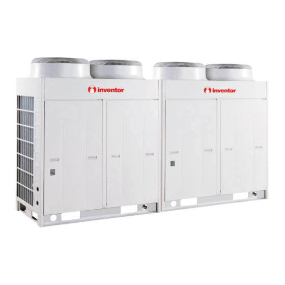
Page 112: Dimensions Data
MODULAR D.C. INVERTER MULTI VRF INSTALLATION 3.3 Dimensions Data ◆ INV-Pdm224W/NaB-M, INV-Pdm280W/NaB-M Outline dimensions. (Unit: mm) (The picture of the units is only for reference, everything goes by with the real object) ◆ INV-Pdm335W/NaB-M, INV-Pdm400W/NaB-M, INV-Pdm450W/NaB-M Outline dimensions. (Unit: mm) -
Page 113: Clearance Data
MODULAR D.C. INVERTER MULTI VRF INSTALLATION 3.4 Clearance Data ① Clearance data of single unit Electrical Box. Outlet on this side. The wall on the four side of the outdoor unit should be in accordance with the above basic space requirement; In case that the front side and left side (or right side) of the outdoor unit is open space: No restriction to wall height 对墙壁的高度没有限制... - Page 114 MODULAR D.C. INVERTER MULTI VRF INSTALLATION ② Clearance data of multiple unit To ensure good ventilation, the top of unit shall be kept open and free of any obstructions. In case that the front side and left side (or right side) of the outdoor unit is open space, the unit shall be installed in the same direction.
-
Page 115: Take Monsoons And Snow Into Consideration
MODULAR D.C. INVERTER MULTI VRF INSTALLATION 3.5 Take Monsoons and Snow into Consideration The monsoon shall be taken into consideration when installing the outdoor unit. Correct Incorrect 正确 正确 不正确 Correct Protective 防护罩 cover 新风吸入口 新风吸入口 Fresh air Fresh air suction 新风吸入口... -
Page 116: Installation Of Indoor Unit
The air conditioner unit installed in the following place may have malfunction, if the malfunction cannot prevent, please contact the Nominated Repair Center Of INVENTOR. ① the place with greasy all around; ② the seashore place with salinity and alkali; ③ the place with vulcanized gas( such as vulcanized hot spring);... - Page 117 MODULAR D.C. INVERTER MULTI VRF INSTALLATION The following figure is applicable to the indoor units of INV(L)-R22P/Na-K, INV(L)-R25P/Na-K,INV(L)-R28P/Na-K,INV(L)-R36P/Na-K Electric box Nameplate Liquid pipe Gas pipe Rear air return vent Drainage pipe Lower air return following figure applicable indoor units INV(L)-R45P/Na-K,INV(L)-R50P/Na-K,INV(L)-R56P/Na-K,INV(L)-R63P/Na-K,INV(L)-R71P/Na-K,IN V(L)-R80P/Na-K,INV(L)-R90P/Na-K,INV(L)-R112P/Na-K,INV(L)-R125P/Na-K,INV(L)-R140P/Na-K Model A(mm)
- Page 118 MODULAR D.C. INVERTER MULTI VRF INSTALLATION INV(L)-R90P/ Na-K 1382 1155 1340 1425 1278 1382 1155 1340 1425 1278 INV(L)-R112P/ Na-K INV(L)-R125P/ Na-K 1382 1155 1340 1425 1278 INV(L)-R140P/ Na-K 1382 1155 1340 1425 1278 Drainage pipe Model H(mm) I(mm) J(mm) Liquid pipe(inch) Gas pipe(inch) (Outer ×Inner)...
- Page 119 MODULAR D.C. INVERTER MULTI VRF INSTALLATION 4.1.3 Clearance data Nut with washer Nut spring 4.1.4 Installation demonstration ① Selection of style of return air Wind supply Wind supply Air supply Air supply Back wind Return air Back wind Return air Install the back wind pipe(b) Install the back wind pipe (a) Install the return air duct...
-
Page 120: Cassette Type
MODULAR D.C. INVERTER MULTI VRF INSTALLATION ③ Installation of supply air duct Ceiling hoisting Wind supply Back wind Return air Air supply Back wind Return air Return air Ducted type Return air Name Hoisting Supply air bent outlet duct indoor unit inlet Note:Fig.6 only shows the install of rear return air... - Page 121 Please contact the local INVENTOR special nominated repair department before installation. Any malfunction caused by the unit that is installed by the department that is not special nominated by INVENTOR would not deal with on time by the inconvenience of the business contact.
- Page 122 MODULAR D.C. INVERTER MULTI VRF INSTALLATION 4.2.2 Dimensions Data INV(L)-R140T/Na-K, INV(L)-R125T/Na-K, INV(L)-R112T/Na-K, INV(L)-R100T/Na-K, INV(L)-R90T/Na-K, INV(L)-R80T/Na-K, INV(L)-R71T/Na-K, INV(L)-R63T/Na-K, INV(L)-R56T/ Na-K , INV(L)-R50T/Na-K, INV(L)-R45T/Na-K , INV(L)-R36T/Na-K, INV(L)-R28T/ Na-K Refrigerant pipe Hoisting screw (X4) 680( Gaps between hoisting screw rods 840( Indoor unit 890( Ceiling opening 950(...
- Page 123 I N V I N V I N V I N V I N V I N V I N V I N V I N V I N V I N V I N V I N V...
- Page 124 MODULAR D.C. INVERTER MULTI VRF INSTALLATION Nut (supplied at scene) Gasket (attachment) Insert Hoisting stand Gasket anchor board Tighten (double nuts) (attachment) [ Fix the hoisting stand firmly ] [ Fix the gasket firmly ] Bolt of one of the angle of outlet pipe is fix on the angle of the drainage slot Center of the ceiling opening...
- Page 125 MODULAR D.C. INVERTER MULTI VRF INSTALLATION Smear freeze motoroil here Median sponge (attachment) (entwine the wiring interface with seal mat) Thread fasten(x4) Torque wrench Heat preservation sheath of liquid inlet tube (attachment) (for liquid tube) Heat preservation Spanner sheath of gas collection tube (attachment)(for Gas collection tube gas tube)
- Page 126 MODULAR D.C. INVERTER MULTI VRF INSTALLATION ☆ Heat insulation should be done to indoor Sponge(attachment) drain hose. Drain stepup pipe note Clamp Clamp(attachment) ☆ The install height of the drain raising pipe should less than 280mm. ☆ The drain raising pipe should form a right Sponge (gray) Drain hose Below 4mm...
- Page 127 MODULAR D.C. INVERTER MULTI VRF INSTALLATION [ Way of immiting ] Drain hose Test hole cover Drain vent for repair use (plastic stopper is included) (drain the water in waterspout by this outlet vent) Test hole < Immiting water from the rest hole > Above100mm Plastic water pot (The length of the pipe should be about 100mm.)
-
Page 128: Floor Ceiling Type
MODULAR D.C. INVERTER MULTI VRF INSTALLATION 4.3 Floor Ceiling Type 4.3.1 Selection of installation site Selection of Installation Location for Air Conditioner Unit The installation of air conditioner unit must be in accordance with national and local safety codes. Installation quality will directly affect the normal use of air conditioner unit. The user is prohibited from installation by himself. - Page 129 MODULAR D.C. INVERTER MULTI VRF INSTALLATION 4.3.2 Dimensions Data Installation dimensions Outline dimensions Model INVL-R28Zd/Na-K INV-R28Zd/Na-K INVL-R36Zd/Na-K INV-R36Zd/Na-K INV(L-R50Zd/Na-K INV-R50Zd/Na-K INVL-R71Zd/Na-K 1220 1300 INV-R71Zd/Na-K INVL-R90Zd/Na-K 1500 1590 INV-R90Zd/Na-K INVL-R112Zd/Na-K 1500 1590 INV-R112Zd/Na-K INVL-R125Zd/Na-K 1500 1590 INV-R125Zd/Na-K...
-
Page 130: Ceiling Type
MODULAR D.C. INVERTER MULTI VRF INSTALLATION 4.3.3 Clearance data ☆ The space around the unit is adequate for ventilation (Refer to Fig.1) Fig.1 4.3.4 Installation demonstration ● There are 2 styles of installation ☆ Ceiling type ☆ Floor type Each type is similar to the other as follows: 1. - Page 131 MODULAR D.C. INVERTER MULTI VRF INSTALLATION 3. Set the suspension bolt. (Use W3/8 or M10 size suspension bolts) ☆ Adjust the distance from the unit to the ceiling slab beforehand (Refer to Fig.4) 4. Fix the hanger bracket to the suspension bolt. !...
- Page 132 MODULAR D.C. INVERTER MULTI VRF INSTALLATION...
-
Page 133: Wall Mounted Type
INVENTOR would not deal with on time by the inconvenience of the business contact. It should be guide under the professional personnel when the air conditioner unit is moved to other... - Page 134 MODULAR D.C. INVERTER MULTI VRF INSTALLATION...
- Page 135 MODULAR D.C. INVERTER MULTI VRF INSTALLATION 4.4.3 Installation demonstration Fig.1 1. Find the horizontal position by seton method; since the drainage pipe is on the left side, adjust the rear panel to make its left side a little bit lower. 2.
-
Page 136: Installation Requirements Of Refrigerant Piping
MODULAR D.C. INVERTER MULTI VRF INSTALLATION 5 INSTALLATION REQUIREMENTS OF REFRIGERANT PIPING 5.1 Specification R410a refrigerant system External External Thickness(mm) Thickness(mm) Diameter(mm/inch) Diameter(mm/inch) φ6.35 ≥0.8 φ25.4 ≥1.5 φ9.52 ≥0.8 φ28.6 ≥1.5 φ12.7 ≥1 φ34.9 ≥1.5 φ15.9 ≥1 φ41.3 ≥2.0 φ19.05 ≥1 φ44.5 ≥2.0... - Page 137 MODULAR D.C. INVERTER MULTI VRF INSTALLATION 5.2.2 For outdoor unit with total rated capacity more than or equal to 20.0kW and less than 60.0kW(See the above picture for the piping methods) Allowable (m/ft) Fitting pipe value +…+L +a+b+…+i Total length (actual length) of fitting pipe 300/984 Actual length 100/328...
- Page 138 MODULAR D.C. INVERTER MULTI VRF INSTALLATION 5.3 Selection of Y-Type Branch Pipe Total Capacity of the Downstream R410a refrigerant system Model Indoor Unit (X) X≤200 FQ01A 200<X≦300 FQ01B Y-Type Branch Pipe 300<X≦700 FQ02 700<X≦1350 FQ03 1350<X FQ04 5.4 Selection of Diameter ①...
- Page 139 MODULAR D.C. INVERTER MULTI VRF INSTALLATION Notes Model Name Illustration ML01- Liquid pipe Sub-assembly corresponding ML01 to outdoor module ML01- Air pipe 2)Selection of pipe diameter between module and module Pipe between outdoor unit and 室外机与连接组件间配管 connection sub-assembly Pipe between outdoor unit and 室外机与连接组件间配管...
-
Page 140: Installation Of Refrigerant Piping
MODULAR D.C. INVERTER MULTI VRF INSTALLATION 6 INSTALLATION OF REFRIGERANT PIPING 6.1 Flow Chart of Installation Installation of 安装室内机 indoor unit Fabrication according to 按配管设计尺寸加工 piping design dimension Installation of 安装连接管 connection pipes Expel with nitrogen 置换氮气 纤锡焊接 Welding Purge 吹净... - Page 141 MODULAR D.C. INVERTER MULTI VRF INSTALLATION 6.3 Installation of Metal Embedded Pipe Work Order Metal Embedding Installation of Metal Plotting Diagram Embedded Parts Plot the line on ground if possible and use laser to project it onto the roof. This is quick and correct. ...
- Page 142 MODULAR D.C. INVERTER MULTI VRF INSTALLATION 6.5 Management and Machining of Refrigerant Piping 1)Storage After receiving the refrigerant pipe and other components, do not move them to the storage until confirming that they have no deformation, bend, crack or damage. ...
- Page 143 MODULAR D.C. INVERTER MULTI VRF INSTALLATION a) Cut vertically to axis direction by using special pipe cutter that is suitable to the dimension of copper pipe (big, medium, small). b) During operation, press and rotate the pipe cutter slowly and cut off the copper pipe without causing any deformation.
- Page 144 MODULAR D.C. INVERTER MULTI VRF INSTALLATION d) Machining with electric pipe bender (hydraulic)……Suitable for mass machining of fine and coarse fitting pipes (φ6.35mm-φ69.9mm). Advantage ※ Decrease the weld joint, thus reduce the possibility of leakage and oxidization. For example: It can decrease the weld by 8 spots. Please act now to improve the quality. ※...
- Page 145 MODULAR D.C. INVERTER MULTI VRF INSTALLATION side of pipe with alcohol) to ensure no dust and no water in pipeline Nitrogen-filled welding shall be used for the welding of copper pipes. Nitrogen pressure shall be 0.5±0.1kgf/cm . Nitrogen flow can be sensed by hand. ...
- Page 146 If the pipe size selected on site is different from the size of branch connector, please use the pipe cutter to cut from the middle of different connection pipes and remove the burrs. Then, insert the copper pipe to appropriate depth. The branch pipes from INVENTOR are all provided with positioning mark. Branch pipe...
- Page 147 MODULAR D.C. INVERTER MULTI VRF INSTALLATION Do not use the connection method that the copper pipe is cased on branch pipe of smaller diameter. Branch pipe Copper pipe Correct connection Wrong connection The copper pipe shall not be inserted into the branch pipe too deep. Branch pipe Copper pipe Correct connection...
- Page 148 MODULAR D.C. INVERTER MULTI VRF INSTALLATION i. Locations marked with ―Staff Only‖ shall be indicated. j. An application is necessary for use of open flame and shall be reviewed by on-site safety officer for approval. k. Instructions given by fire authorities shall be accepted in accordance with local laws and regulations. l.
- Page 149 MODULAR D.C. INVERTER MULTI VRF INSTALLATION 4) Operation order Basic procedures for welding: Assemble copper pipes Cleaning Check whether clearance is proper. Fill nitrogen N2 Nitrogen pressure 0.05-0.3Mpa Welding heating Welding flux Acknowledge welding flux Add welding flux Cooling, continue to fill nitrogen for over 10s Shut off nitrogen Make visual inspection to...
- Page 150 MODULAR D.C. INVERTER MULTI VRF INSTALLATION ◆ When nitrogen is charged, the press switch on the quick connector and inflator shall be closed to let nitrogen totally filled in the pipe. ◆ Make sure nitrogen reaches all welding connectors in order to effectively discharge air ◆...
- Page 151 MODULAR D.C. INVERTER MULTI VRF INSTALLATION ◆ Braze welding shall be easy to operate downward or in transverse direction. In upward operation, brazing filler metal is prone to fall so that high skills are required. Solder Solder Weld torch Weld torch Solder Transverse Weld torch...
- Page 152 MODULAR D.C. INVERTER MULTI VRF INSTALLATION welding) in the piping. 1)Main purposes of cleaning are as follows: To eliminate oxide caused by insufficiency of nitrogen-filled protection during pipe welding. To remove foreign substances and water that may enter the piping due to improper storage and transport.
- Page 153 MODULAR D.C. INVERTER MULTI VRF INSTALLATION 6.9 Pressure Maintaining and Leak Hunting 1)Pressure maintaining of refrigerant piping After refrigerant piping of a system is welded, A refrigerant filling nozzle shall be welded respectively on the big pipe and on the small pipe on the outdoor unit side.
- Page 154 MODULAR D.C. INVERTER MULTI VRF INSTALLATION indoor unit and outdoor unit) When refrigerant piping is to be installed, pressure maintaining and leak hunting is required for the piping. After refrigerant piping is in connection with indoor unit and outdoor unit, pressure maintaining and leak hunting is also required.
- Page 155 MODULAR D.C. INVERTER MULTI VRF INSTALLATION Lower foam of thermal Upper foam of thermal insulation insulation 3)Cautions: The thermal insulation materials shall be able to withstand the pipe temperature. For heat pump unit, it is required to withstand a temperature not lower than 70℃ on liquid pipe side and not lower than 120℃ on gas pipe side.
- Page 156 MODULAR D.C. INVERTER MULTI VRF INSTALLATION obtained) Exhaust flow is high (over 40L/min). The following vacuum pumps are recommended: Maximum vacuum air Model displacement Air discharge Vacuum drying Lubricant shaft pump 100L/min Suitable Suitable Non-lubricant shaft 50L/min Suitable Suitable pump Comparison table of different pressure units is as follows: Standard air...
- Page 157 MODULAR D.C. INVERTER MULTI VRF INSTALLATION Amount of refrigerant charge for every meter of liquid pipe(kg/m) Φ22.2 Φ19.05 Φ15.9 Φ12.7 Φ9.52 Φ6.35 0.35 0.25 0.17 0.11 0.054 0.022 Note: a. Standard pipe length is 15m. If refrigerant piping (L) is shorter than or equal to 15m, no additional refrigerant is needed If piping is longer than 15m (based on liquid pipe), more refrigerant shall be added.
-
Page 158: Installation Of Electronic Expansion Valve Parts
MODULAR D.C. INVERTER MULTI VRF INSTALLATION 7 INSTALLATION OF ELECTRONIC EXPANSION VALVE PARTS 7.1 Direction Requirements To ensure normal operation of the unit, please connect the electronic expansion valve sub-assembly as shown below. Ensure that the vertical arrow labeled on electronic expansion valve sub-assembly is pointed upward. To Outdoor To Indoor Unit... - Page 159 MODULAR D.C. INVERTER MULTI VRF INSTALLATION WARNING: The length of connection pipe must be 1m≤L≤1. 5m. The electronic expansion valve sub-assembly must be connected to the indoor and outdoor unit in a direction as marked. If connected in reverse direction, severe error will be caused to the unit. (3)...
-
Page 160: Installation Of Condensate Pipe
MODULAR D.C. INVERTER MULTI VRF INSTALLATION 8 INSTALLATION OF CONDENSATE PIPE 8.1 Material Quality Requirements for Condensate Pipe Generally, the condensate pipe shall be water supply U-PVC pipe, adhered by using special glue. The other materials available include: PP-R pipe, PP-C pipe and hot-dipped galvanized steel pipe. It is not allowed to use aluminum plastic composite pipe. - Page 161 MODULAR D.C. INVERTER MULTI VRF INSTALLATION 6) Confluence toward the horizontal pipe shall be best from the upper. Back flow is easy to occur if from the lengthwise direction. Indoor Unit Mounting of horizontal pipe Main pipe Main pipe Main pipe 7) Do not tie the condensate pipe and refrigerant pipe together.
- Page 162 MODULAR D.C. INVERTER MULTI VRF INSTALLATION The auxiliary drainage pipe must be thermally insulated: 冷凝水管 Thermal insulation of condensate pipe 保温层 Pipe cover 管盖 15) The long drainage pipe may be fixed by using hanger bolts, thus to ensure a gradient of 1/100 (PVC cannot be bent).
-
Page 163: Installation Of Drainage Pipe For Different Types Of Indoor Unit
MODULAR D.C. INVERTER MULTI VRF INSTALLATION The horizontal pipe cannot be connected to the vertical pipe at a same height. It can be connected in a manner as shown below: N01: 3-way connection of drainage pipe joint 3-way connection of drainage pipe joint NO2: Connection of drain elbow Connection of... - Page 164 MODULAR D.C. INVERTER MULTI VRF INSTALLATION Gradient over 1/100 Use drainage pipe and clamp. Insert the drainage hose to the root. From the middle of white tape, tighten the clamp until the tightening distance to the screw head is shorter than 4mm. A) For thermal isolation, use sealing tape to wrap the drainage pipe and clamp.
- Page 165 MODULAR D.C. INVERTER MULTI VRF INSTALLATION T-joint collecting drainage pipe Over 100mm Fig. The specification of collecting drainage pipe shall be suitable to the working capacity of the unit We may collect the drainage pipes of all the indoor units in one system (An outdoor unit and all the indoor units connected to this outdoor unit are called one system), or collect the drainage pipes of all the indoor units in several systems.
- Page 166 MODULAR D.C. INVERTER MULTI VRF INSTALLATION The indoor drainage hose shall be thermally insulated. Big sponge (accessory) Clamp (accessory) Clamp Drainage hose Below 4mm Sponge (grey) To connect the drainage pipes for multiple machines, please use the method of multi-pipe collection, as shown below Introduce water here for water test...
-
Page 167: Test For Condensate Pipe
MODULAR D.C. INVERTER MULTI VRF INSTALLATION Protrusion Twisting Do not immerse in water. The extended section of drainage hose shall be wrapped with thermal insulation sheath when passing the room. Thermal insulation of condensate pipe Pipe cover Fig.3.41 After installation of the drainage pipe, be sure to make water test and check if the water can be drained smoothly. -
Page 168: Requirements Of Heat Preservation
MODULAR D.C. INVERTER MULTI VRF INSTALLATION unit if the drainage is thorough and if there is any water deposit. If any, readjust it. If not, complete the water test and proceed to the thermal insulation on all pipe joints. 8.5 Requirements of Heat preservation ... -
Page 169: Electrical Installation
MODULAR D.C. INVERTER MULTI VRF INSTALLATION 9 ELECTRICAL INSTALLATION 9.1 Precautions for Electrical Installation Itemized Description of Cautions. The electrical installation must be done by professional electricians. The electrical installation must be done in accordance with applicable technical codes and other rules. -
Page 170: Specifications Of Power Cord & Circuit Breaker
Wire diameter for Model Power switch each wire Numb each combination unit capacit combination diamete unit 380V 3N~ INV-Pdm224W/NaB-M 50Hz 380V 3N~ INV-Pdm280W/NaB-M 50Hz 380V 3N~ INV-Pdm335W/NaB-M 10.0 10.0 50Hz 380V 3N~ INV-Pdm400W/NaB-M 10.0 10.0 50Hz 380V 3N~... -
Page 171: Wiring Sketch Map
MODULAR D.C. INVERTER MULTI VRF INSTALLATION 9.3 Wiring Sketch Map Wiring Sketch Map between Outdoor Unit maximum 4 outdoor unit outdoor unit outdoor unit sets Machine unit Machine unit electric box electric box Machine unit electric box Terminal Terminal board Power board Terminal... -
Page 172: Dial-Up Of Unit
INVENTOR COMMERCIAL AIR CONDITION MODULAR D.C. INVERTER MULTI VRF 9.4 Dial-up of Unit 9.4.1 The mainboard of the indoor unit and wire controller dial-up 1) Address code Address dial-up must be set for the multi indoor units; otherwise the abnormal communication will be caused to the unit. - Page 173 INVENTOR COMMERCIAL AIR CONDITION MODULAR D.C. INVERTER MULTI VRF Address 8, dial-up value 0111 Address 8, dial-up value 1010 2)Capacity Code On the mainboard of indoor unit, two 4-bit DIP switches are used to distribute the address and capacity of indoor units. The 4-bit DIP switch (marked with ―capacity‖ below) used for setting the capacity of indoor units is factory set before shipment of indoor unit, while it is covered by sealant, so that it cannot be changed by the user.
- Page 174 INVENTOR COMMERCIAL AIR CONDITION MODULAR D.C. INVERTER MULTI VRF meet the normal operating of the units. Dial-up switch SW3 Module address ―0‖ (ON position). Note to keep the module address in conformity. 3)Quantity dial-up ☆ The module quantity dial-up connected by the units is 2-bit dial-up switch, and the mainboard position is SW2.
- Page 175 INVENTOR COMMERCIAL AIR CONDITION MODULAR D.C. INVERTER MULTI VRF MAINTENANCE...
-
Page 176: Maintenance
MODULAR D.C. INVERTER MULTI VRF MAINTENANCE MAINTENANCE 1 TROUBLE TABLES 1.1 Trouble Display of Indoor Unit 1.1.1 Trouble display of wire remote controller Error Error Code High-pressure protection Prevention against low temperature Low-pressure protection Exhaust overtemperature Overcurrent Protector Communication error Water-full protection Indoor ambient... - Page 177 MODULAR D.C. INVERTER MULTI VRF MAINTENANCE 1.1.2 Trouble display of mainboard LED of duct type indoor unit Error Error Error Error Code Code Error with oil temperature Prevention against low temperature sensor 2 (digital) Outdoor ambient temperature sensor Indoor ambient temperature error sensor error Outdoor tube-inlet sensor error...
- Page 178 MODULAR D.C. INVERTER MULTI VRF MAINTENANCE Timer Blin Blink Blink Bright blink Dark Lamp Notes: [1] Bright and dark intermittently; [2] Bright and dark simultaneously 1.1.6 Trouble display of mainboard LED of Ling Ge Feng Error Error Code Error Error Code Prevention against low Error with oil temperature temperature...
-
Page 179: Trouble And State Display Of Mainboard Led Of Outdoor Unit
MODULAR D.C. INVERTER MULTI VRF MAINTENANCE 1.2 Trouble and State Display of Mainboard LED of Outdoor Unit Description of indicator LED. Difinition: LED6: LED5: LED4, LED3, LED2, LED1: Transfer Drive board of Drive board of Main control display of the outdoor units board compressor fan motor... - Page 180 MODULAR D.C. INVERTER MULTI VRF MAINTENANCE Temperature drift ○ ● ○ ◎ ◎ ○ ○ ◎ ◎ protection Error with ○ ● ◎ ○ ◎ ○ ◎ ● ○ temperature sensor on drive board ○ ○ ○ ● ○ ○ ●...
- Page 181 MODULAR D.C. INVERTER MULTI VRF MAINTENANCE Variable-frequency casing ● ● ○ ○ ◎ ◎ temperature sensor error Fixed frequency 1 ○ ● ○ ○ ◎ ◎ error with sensor of housing head cover Fixed frequency 2 ● ◎ ● ○ ◎...
- Page 182 MODULAR D.C. INVERTER MULTI VRF MAINTENANCE 1.3 Number of indoor units display Lamp display Number of indoor units LED6 LED5 LED4 LED3 LED2 LED1 ● ● ● ● ● ○ ● ● ● ● ○ ● ● ● ● ● ○...
-
Page 183: Flow Chart Of Troubleshooting
MODULAR D.C. INVERTER MULTI VRF MAINTENANCE 2 FLOW CHART OF TROUBLESHOOTING The repair personnel shall collect the error information as more as possible for careful study and list those electric or system parts that might cause the error. Then, the repair personnel shall be able to identify the specific cause of error and find out the problem parts. - Page 184 MODULAR D.C. INVERTER MULTI VRF MAINTENANCE 高压保护 High-pressure protection 用压力表 测量 否 是 Measure if the Use pressure gauge to 测量其压力是否为 压力开关是否 更换室外机主板 pressure switch is Replace the mainboard of outdoor unit measure if the pressure is normal? really high? 真正高压?...
- Page 185 MODULAR D.C. INVERTER MULTI VRF MAINTENANCE Low-pressure Protection 2) Error display on hand controller: E3 Outdoor units mainboard indicator: led4: dark; led3: dark; led2: blink; led1: dark (low voltage) led4: blink; led3: blink; led2: bright; led1: dark (lack of refrigerant) Indoor units mainboard indicators: Patio indoor units: red led: blink:red led:blink;...
- Page 186 MODULAR D.C. INVERTER MULTI VRF MAINTENANCE 低压保护 Low-pressure protection 用压力 否 Use pressure gauge to 表测量压力是否真正 参照低压传感器故障 Refer to low pressure sensor error measure if the pressure 为低压? is really low? 是 检查 是 依据铭牌所标称的制冷剂量和 Add refrigerant according to the nominal refrigerant volume Check if the refrigerant in 系统中制冷剂量是否...
- Page 187 MODULAR D.C. INVERTER MULTI VRF MAINTENANCE Exhaust Temperature Protection Error display on hand controller: E4 Outdoor units mainboard indicator: led4: dark; led3: dark; led2: blink; led1: blink Indoor units mainboard indicators: Patio indoor units: red led: blink:red led:blink; green led:dark; yellow led:dark FY wall-mounting motor: red led:blink;...
- Page 188 MODULAR D.C. INVERTER MULTI VRF MAINTENANCE 排气温度保护 Exhaust Temperature Protection 测量压缩机 测量 Measure if the 否 否 Measure if the exhaust resistance of 排气温度是否已到 感温包阻值是否 temperature of compressor temperature sensor 118℃? 正确? reaches 118℃? is correct? 是 是 检查当压缩机排气温度 否 When the exhaust 更换室外机主板...
- Page 189 MODULAR D.C. INVERTER MULTI VRF MAINTENANCE 3) E5 Protection Error display on hand controller: E5 Outdoor units mainboard indicator: / Indoor units mainboard indicators: Patio indoor units: red led: blink:red led:blink; green led:dark; yellow led:dark FY wall-mounting motor: red led:blink; yellow led:dark New FY wall-mounting motor: red led:blink;...
- Page 190 MODULAR D.C. INVERTER MULTI VRF MAINTENANCE Communication Failure 4) Error display on hand controller: E6 Outdoor units mainboard indicator: led4: dark; led3: blink; led2: blink; led1:dark Indoor units mainboard indicators: Patio indoor units: red led: blink:red led:blink; green led:blink; yellow led:blink FY wall-mounting motor: red led:blink(dark at the same time);...
- Page 191 MODULAR D.C. INVERTER MULTI VRF MAINTENANCE Temperature sensor Trouble 5) 1. Outdoor ambient temperature sensor error Error display on hand controller: F4 Outdoor units mainboard indicator: led4: dark; led3: dark; led2: dark; led1: dark Indoor units mainboard indicators: Patio indoor units: red led: blink:red led:blink; green led:dark; yellow led:dark FY wall-mounting motor: red led:blink;...
- Page 192 MODULAR D.C. INVERTER MULTI VRF MAINTENANCE Sensor Trouble 6) 1. High-voltage sensor error Error display on hand controller: Fc Outdoor units mainboard indicator: led4: bright; led3: blink; led2: blink; led1: blink Indoor units mainboard indicators: Patio indoor units: red led: blink:red led:blink; green led:dark; yellow led:dark FY wall-mounting motor: red led:blink;...
- Page 193 MODULAR D.C. INVERTER MULTI VRF MAINTENANCE 7) No energization to the unit and mainboard No energization to the 机组及主板不得电 unit and mainboard Check the units Check if the power 否 检查机组内主接线板 检查接线板电源是否 main wiring board of wiring board is in L1;N电压是否为220V 有故障...
- Page 194 MODULAR D.C. INVERTER MULTI VRF MAINTENANCE The AC contactor does not pull in 8) The AC contactor of 压缩机交流接触器不吸合 compressor does not pull in Check corresponding 否 If the units in normal 机组是否处于正常开机 按照手操器显示的故障 content according to the start-up state(no 状态(无故障显示)...
- Page 195 MODULAR D.C. INVERTER MULTI VRF MAINTENANCE 9) Typical Troubleshooting (E5) for DC frequency conversion drive board 1. Communication error between frequency conversion and main control Communication error 变频驱动到主控通讯 between frequency 故障 conversion and main control 否 Check if the drive If the drive still works 驱动是否在工作,指示...
- Page 196 MODULAR D.C. INVERTER MULTI VRF MAINTENANCE 2. The temperature of radiating fin is too high The temperature of 散热片温度过高 radiating fin is too high 否 If the outdoor units are 室外机散热通 Improve ventilation in good heat radiation 改善通风情况 condition. 风是否良好? and ventilation.
- Page 197 MODULAR D.C. INVERTER MULTI VRF MAINTENANCE 3. Excessive high/low protection of DC input voltage Excessive high/low protection of 直流输入电压过高/低保护 DC input voltage 否 Check if the three-phase 检查三相电源是否平衡? Improve rectifier power is balancing, and 改善整机电源 电压在320V~457V之间 if the voltage is between power 320V-457V.
- Page 198 MODULAR D.C. INVERTER MULTI VRF MAINTENANCE 4. IPM ABNORMAL IPM abnormal IPM异常 否 Connect phase If the phase sequence 压缩机相序接线 接U,V,W相序接 sequence wire U, wire of the compressor 是否正常? 线 V, W, is normal. 是 否 Increase magnetic if the compressor wire is 压缩机接线...
-
Page 199: Wiring Diadram
MODULAR D.C. INVERTER MULTI VRF MAINTENANCE 3 WIRING DIADRAM 1) Model:INV-Pdm224W/NaB-M, INV-Pdm280W/NaB-M Model:INV-Pdm335W/NaB-M, INV-Pdm400W/NaB-M, INV-Pdm450W/NaB-M... - Page 200 MODULAR D.C. INVERTER MULTI VRF MAINTENANCE Indoor unit INV-R22P/Na-K, INV-R25P/Na-K, INV-R28P/Na-K, INV-R36P/Na-K, INVL-R22P/Na-K, INVL-R25P/Na-K, INVL-R28P/Na-K, INVL-R36P/Na-K INV-R45P/Na-K , INV-R50P/Na-K, INVL-R45P/Na-K INVL-R50P/Na-K:...
- Page 201 MODULAR D.C. INVERTER MULTI VRF MAINTENANCE INV-R56P/Na-K, INV-R71P/Na-K, INV-R80P/Na-K, INVL-R56P/Na-K, INVL-R71P/Na-K, INVL-R80P/Na-K INV-R90P/Na-K, INV-R112P/Na-K, INV-R140P/Na-K, INVL-R90P/Na-K, INVL-R112P/Na-K, INVL-R140P/Na-K INV-R125P/Na-K, INVL-R125P/Na-K...
- Page 202 MODULAR D.C. INVERTER MULTI VRF MAINTENANCE INV-R22P/NaB-K, INV-R25P/NaB-K, INV-R28P/NaB-K, INV-R32P/NaB-K, INV-R36P/NaB-K 63624640 INV-R28T/Na-K, INV-R36T/Na-K, INV-R45T/Na-K, INV-R50T/Na-K, INV-R56T/Na-K, INV-R71T/Na-K,...
- Page 203 MODULAR D.C. INVERTER MULTI VRF MAINTENANCE INV-R80T/Na-K, INV-R90T/Na-K, INV-R112T/Na-K, INV-R125T/Na-K, INVL-R28T/Na-K, INVL-R36T/Na-K, INVL-R45T/Na-K, INVL-R50T/Na-K, INVL-R56T/Na-K, INVL-R71T/Na-K, INVL-R80T/Na-K, INVL-R90T/Na-K, INVL-R112T/Na-K, INVL-R125T/Na-K Swing Motor Limit Switch Water Level Switch Environment Temp.sensor Temp.sensor Temp.sensor Manual Panel Temp.sensor INV-R22G/NaB-K, INVL-R22G/NaB-K, INV-R28G/NaB-K, INVL-R28G/NaB-K, INV-R36G/NaB-K, INVL-R36G/NaB-K, INV-R45G/NaB-K, INVL-R45G/NaB-K INV-R50G/NaB-K, INV-R56G/NaB-K, INVL-R50G/NaB-K, INVL-R56G/NaB-K...
- Page 204 MODULAR D.C. INVERTER MULTI VRF MAINTENANCE INV-R22G/NaC-K,INV-R28G/NaC-K , INV-R36G/NaC-K, INV-R45G/NaC-K, INVL-R22G/NaC-K, INVL-R28G/NaC-K , INVL-R36G/NaC-K, INVL-R45G/NaC-K...
- Page 205 MODULAR D.C. INVERTER MULTI VRF MAINTENANCE INV-R71G/Na-K, INV-R80G/Na-K, INVL-R71G/Na-K, INVL-R80G/Na-K INV-R28Zd/Na-K, INV-R36Zd/Na-K, INV-R50Zd/Na-K, INV-R71Zd/Na-K, INV-R90Zd/Na-K, INV-R112Zd/Na-K, INV-R125Zd/Na-K, INVL-R28Zd/Na-K, INVL-R36Zd/Na-K, INVL-R50Zd/Na-K, INVL-R71Zd/Na-K, INVL-R90Zd/Na-K, INVL-R112Zd/Na-K, INVL-R125Zd/Na-K...
-
Page 206: Disassembly And Assembly Procedure Of Main Parts
MODULAR D.C. INVERTER MULTI VRF MAINTENANCE 4 DISASSEMBLY AND ASSEMBLY PROCEDURE OF MAIN PARTS 4.1Outdoor Unit Removal and Installation of Compressor Remark: Before removing the compressor, make sure that there is no refrigerant inside the pipe system and that the power has been cut off. - Page 207 ● Remove the compressor from 5. Remove the compressor chassis ● Put the new compressor to 6. Fix the new compressor to correct position. ● Firstly, use spanner to tighten chassis the bolts fixing the compressor. ●No inversion while install compressor.
- Page 208 Disassembly and Assembly of 4-way valve Remarks: Before removing the 4-way valve, make sure that there is no refrigerant inside the pipe system and that the power has been cut off. Step Illustration Handling Instruction ●Remove the left and right front 1.
- Page 209 ● Install the new 4-way valve to 6 Install new 4-way valve correct position. ● Connect the new 4-way valve to the pipe. ● When welding the 4-way valve, please wrap the valve body with wet cloth, thus to prevent the guide inside the valve body from burn.
- Page 210 Removal and Installation of Electronic Expansion Valve Remarks: Before removing Electronic Expansion Valve, make sure that there is no refrigerant inside the pipe system and that the power has been cut off. Step Illustration Handling Instruction ●Dismantle the left and right 1.
- Page 211 ● Assemble the coil of electronic 5. Assemble the coil electronic expansion valve. expansion valve ● Check if the elements and 6. Check and fix the front plate. wires are connected correctly. ●After that, cover both sides of the front plate, and fix nuts.
- Page 212 Removal and Installation of Oil Separator Remarks: Before removing Oil Separator, make sure that there is no refrigerant inside the pipe system and that the power has been cut off. Step Illustration Handling Instruction ●Dismantle the left and right 1 Loosen the fixed nuts front plate and put away;...
- Page 213 ●Fix the fixed nuts 5 Fix the fixed nuts ●Assembly electric heating belt. of oil separator and assembly electric heating belt. ● Check if the elements and 6 Check and fix the front plate. wires are connected correctly. ●After that, cover both sides of the front plate, and fix nuts.
- Page 214 Removal and Installation of Gas-Liquid Separator Remarks: Before removing Gas-Liquid Separator, make sure that there is no refrigerant inside the pipe system and that the power has been cut off. Step Illustration Handling Instruction ●Dismantle the left and right front 1 Loosen the lower fixing coil of the plate and put away;...
- Page 215 ●Move up the right electric box, fixed screws and fix with fixed screws; separator ●Tighten the fixing coil of the right assembly electric heating belt electric box. ●Check if the elements and wires 7 Check and fix the front plate. are connected correctly.
- Page 216 MODULAR D.C. INVERTER MULTI VRF MAINTENANCE ●Use gas welding to heat the 2 Assembly liquid storage tank pipe connections, and then pull them out. Note: During welding, take care not to let the flame burn other elements. ●Adjust and lean the connection 4 Move away the liquid storage tank pipe on the liquid storage tank,...
-
Page 217: Removal And Assembly Of Indoor Unit
4.2 Removal and Assembly of Indoor Unit Single side air-out patio unit Removal and Assembly of Fan Motor Step Illustration Handling Instruction ●Lightly press the 1 Move out the 面板两端的面板开关 Switch of panel front panel assy switch of front panel, thus to loosen one side of the panel, and three snaps on the... - Page 218 ●Use screwdriver to 6 Loosen the 松开这4个螺钉 fixed screws on the fixed screws on Loosen the five screws the five screws the motor top the motor top assy. assy ●Move out the motor 7. Move out the motor top assy. top assy.
- Page 219 ●Assembly water Assembly Tighten the six screws 拧紧这 颗螺钉 water tray and tray filter filter support, support, and tighten the screwdriver to tighten screws the fixed screws on water tray and filter support. ●Assembly the front Assembly 拧紧这 颗螺钉 Tighten the five screws the front panel panel assy and use assy...
- Page 220 Removal and Installation of Drainage Pump Handling Step Illustration Instruction ●Lightly press the 1 Move out the 面板两端的面板开关 Switchs of the panel front panel assy switch front panel, thus loosen one side of panel, three snaps on the opposite would drop off, and then front panel...
- Page 221 ● 7. Remove the Remove water pump water pump and and replace it. replace it. ●Connect 8. Connect the 拧紧这4个螺钉 tighten the 4 screws drainage pipe drainage pipe and use screwdriver to screwdriver to tighten the screws tighten fixing the water screws fixing pump.
- Page 222 Cassette-type Unit Removal and Assembly of Fan Motor Step Illustration Handling Instruction ● Use screwdriver to loosen 1. Loosen the screws fixing the water tray the screws fixing the water tray. ● Remove the water tray 2. Remove the water tray ●...
- Page 223 ● Remove the motor and 6. Remove the motor and replace replace it ● Use screwdriver to tighten 7. Tighten the screws fixing the motor the screws fixing the motor. ● Mount the fan and use 8. Mount the fan and tighten the fixing bolts spanner to tighten the bolts fixing the fan.
- Page 224 Removal and Installation of Drainage Pump Step Illustration Handling Instruction ● 1. Loosen the screws fixing the screwdriver water tray loosen the screws fixing the water tray ● Remove the water pump 2. Remove the water tray and replace it. ●...
- Page 225 Duct type Removal and Assembly of Fan Motor Remarks: Before removing the fan, make sure to cut off the power firstly. Step Illustration Handling Instruction ● Cut off the power supply Unplug motor cables indoor unit. screwdriver to remove the electric cover unplug the motor cables in...
- Page 226 Ultrathin duct type Removal and Assembly of Fan Motor Remarks: Before removing the fan, make sure to cut off the power firstly. Step Illustration Handling Instruction ● Cut off the power supply Unplug motor cables indoor unit. screwdriver to remove the electric box cover and unplug the motor cables in electric box.
- Page 227 ● Assemble the unit in 7. Assemble the unit in reverse to the disassembly reverse to the disassembly procedures procedures and energize it for testing.
- Page 228 Duct-Type Unit (5.6 kW~8.0 kW) Removal and Assembly of Fan Motor Remarks: Before removing the fan, make sure to cut off the power firstly. Step Illustration Handling Instruction ● Cut off the power 1. Unplug the motor cables supply of indoor unit. screwdriver remove the electric box cover and unplug the...
- Page 229 ● Firstly, disengage the 6. Replace the motor motor from motor support. Then, sequentially disengage sub-assembly form the motor shaft. Remove the motor from air inlet and replace with motor. which, for the motor with automatic motor support, motor support shall be removed in advance and then changed to the unit.
- Page 230 Duct-Type Unit(9.0 kW~14 kW) Removal and Assembly of Fan Motor Remarks: Before removing the fan, make sure to cut off the power firstly. Step Illustration Handling Instruction ● Cut off the power Unplug motor supply of indoor unit. Use cables screwdriver to remove the electric box cover and...
- Page 231 ● Assemble the unit in 7. Assemble the unit in reverse to the disassembly reverse to the procedures and energize it disassembly for testing. procedures...
- Page 232 Wall-mounted Unit Removal and Assembly of Fan Motor Remarks: Before removing compressor, make sure that there is no refrigerant inside the pipe system and that the power has been cut off. Step Illustration Handling Instruction ● Firstly, Firstly, remove the screwdriver to loosen front panel, the screws.
-
Page 233: Exploded Views And Part List
5 EXPLODED VIEWS AND PART LIST 5.1 Outdoor Unit 1) Model: Exploded View INV-Pdm224W/NaB-M... - Page 234 INV-Pdm224W/NaB-M parts list Name of part Part code Quantity Left side panel sub-assy 01313256P Leading cover(VPd280)(apricot ash) 26904101 Back cover plate 01313261P Front cover plate 01264142P Windshield(left) 01354102 Condenser assy 01124160 01354103 Windshield(right) Fixing support sub-assy NO.2 01324120P Fixing support sub-assy NO.1...
- Page 235 Lower seat transverse girder 01874115P Package wooden base 51094102 Lower seat lengthways girder sub-assy 01874137P Cover of electrical box 01424136P Terminal board 2-8 42011103 Main Board WZCB31 30220025 Main Board ZQ86 30228606 Radiator SRX11D250 49010605 Radiator 49018761 Main Board WZS901 30229004 AC Contactor LC1D25M7C 44010213...
- Page 236 INV-Pdm280W/NaB-M exploded views...
- Page 237 INV-Pdm280W/NaB-M parts list Name of part Part code Quantity Left side panel sub-assy 01313256P Leading cover(VPd280)(apricot ash) 26904101 Back cover plate 01313261P Front cover plate 01264142P Windshield(left) 01354102 Condenser assy 01124160 01354103 Windshield(right) Fixing support sub-assy NO.2 01324120P Fixing support sub-assy NO.1 01324221P Axes flow wind leaf sub-assy (VPd280)(black) 10338702...
- Page 238 Lower seat transverse girder 01874115P Package wooden base 51094102 Lower seat lengthways girder sub-assy 01874137P Cover of electrical box 01424136P Terminal board 2-8 42011103 Main Board WZCB31 30220025 Main Board ZQ86 30228606 Radiator SRX11D250 49010605 Radiator 49018761 Main Board WZS901 30229004 AC Contactor LC1D25M7C 44010213...
- Page 239 INV-Pdm335W/NaB-M exploded views...
- Page 240 INV-Pdm335W/NaB-M parts list Name of part Part code Quantity Left side panel sub-assy 01314143P Condenser assy 01124165 Motor support 01324179P Motor support sub-assy 01324177P Wind leaf 10358202 Leading cover(VPd450)(apricot ash) 26904112 Motor SWB350A 15704105 Back cover plate 01264159P Fixing support sub-assy 3 01324175P Fixing support sub-assy 1 01324171P...
- Page 241 Cut-off valve sub-assy 07334328 Support sub-assy 01324212P Compressor and it‘s fittings E505DH-49D2Y 99071264 Capillary sub-assy(Oil equalizing) 04104153 Oil separator 07424129 Capillary sub-assy(Oil return) 04104152 Compressor and it‘s fittings E405DHD-38D2Y 00204116 Lower panel sub-assy 01194132P Discharge pipe sub-assy 04634222 Panel Front 2 01544117P Netted mantle 01574102...
- Page 242 INV-Pdm400W/NaB-M exploded views...
- Page 243 INV-Pdm400W/NaB-M parts list Name of part Part code Quantity Left side panel sub-assy 01314143P Condenser assy 01124165 Motor support 01324179P Motor support sub-assy 01324177P Wind leaf 10358202 Leading cover(VPd450)(apricot ash) 26904112 Motor SWB350A 15704105 Back cover plate 01264159P Fixing support sub-assy 3 01324175P Fixing support sub-assy 1 01324171P...
- Page 244 Cut-off valve sub-assy 07334328 Support sub-assy 01324212P Compressor and it‘s fittings E505DH-49D2Y 99071264 Capillary sub-assy(Oil equalizing) 04104153 Oil separator 07424129 Capillary sub-assy(Oil return) 04104152 Compressor and it‘s fittings E405DHD-38D2Y 00204116 Lower panel sub-assy 01194132P Discharge pipe sub-assy 04634222 Panel Front 2 01544117P Netted mantle 01574102...
- Page 245 INV-Pdm450W/NaB-M exploded views...
- Page 246 INV-Pdm450W/NaB-M parts list Name of part Part code Quantity Left side panel sub-assy 01314143P Condenser assy 01124165 Motor support 01324179P Motor support sub-assy 01324177P Wind leaf 10358202 Leading cover(VPd450)(apricot ash) 26904112 Motor SWB350A 15704105 Back cover plate 01264159P Fixing support sub-assy 3 01324175P Fixing support sub-assy 1 01324171P...
- Page 247 Cut-off valve sub-assy 07334328 Support sub-assy 01324212P Compressor and it‘s fittings E605DH-59D2Y 99071264 Capillary sub-assy(Oil equalizing) 04104153 Oil separator 07424129 Capillary sub-assy(Oil return) 04104152 Compressor and it‘s fittings E405DHD-38D2Y 00204116 Lower panel sub-assy 01194132P Discharge pipe sub-assy 04634222 Panel Front 2 01544117P Netted mantle 01574102...
-
Page 248: Indoor Unit
5.2 Indoor Unit 5.2 .1 Exploede diagram of Casstte and list of components ( 1 ) INV(L)-R28T/Na-K, INV(L)-R36T/Na-K, INV(L)-R45T/Na-K, INV(L)-R50T/Na-K, INV(L)-R56T/Na-K, INV(L)-R71T/Na-K, INV(L)-R80T/Na-K Name INV-R28T/Na-K, INVL-R28T/Na-K,... - Page 249 INV-R36T/Na-K INVL-R36T/Na-K Coding Coding Tube Exit Plate 01382710 01382710 Body Fixed Plate 01332701 01332701 Front Side Plate 01302717 01302717 Left Side Plate 01302740 01302740 Base Plate 01222702 01222702 Rear Side Plate 01302719 01302719 Bottom Foam 52012716 52012716 Motor Gasket 76712711 76712711 Bolt 70212701...
- Page 250 INV-R50T/Na-K INVL-R50T/Na-K Coding Coding Tube Exit Plate 01382710 01382710 Body Fixed Plate 01332701 01332701 Front Side Plate 01302717 01302717 Left Side Plate 01302740 01302740 Base Plate 01222702 01222702 Rear Side Plate 01302719 01302719 Bottom Foam 52012716 52012716 Motor Gasket 76712711 76712711 Bolt 70212701...
- Page 251 INV-R56/71/80T/Na-K INVL-R56/71/80T/Na-K Name Coding Coding Tube Exit Plate 01382711 01382711 Body Fixed Plate 01332701 01332701 Front Side Plate 01302718 01302718 Left Side Plate 01302715 01302715 Base Plate 01222702 01222702 Rear Side Plate 01302714 01302714 Bottom Foam 52012711 52012711 Motor Gasket 76712711 76712711 Bolt...
- Page 252 (2) INV(L)-R90T/Na-K, INV(L)-R112T/Na-K, INV(L)-R125T/Na-K Exploded diagram and list of components...
- Page 253 INV-R90/112/125/Na-K INVL-R90/112/125/Na-K Name Coding Coding Tube Exit Plate 01382711 01382711 Body Fixed Plate 01332701 01332701 Front Side Plate 01302713 01302713 Left Side Plate `01302711 `01302711 Base Plate 01222702 01222702 Rear Side Plate 01302709 01302709 Bottom Foam 52012717 52012717 Motor Gasket 76712711 76712711 Bolt...
- Page 254 5.2 .2 Exploded Diagram of Duct and List of Components (1)INV(L)-R22P/Na-K, INV(L)-R25P/Na-K, INV(L)-R28P/Na-K, INV(L)-R32P/Na-K, INV(L)-R36P/Na-K Exploded diagram and list of components...
- Page 255 INV(L)-R28P/Na-K, INV(L)-R22P/Na-K, INV(L)-R32P/Na-K, INV(L)-R25P/Na-K Name INV(L)-R36P/Na-K Coding Coding Top Cover Sub-assy 01259052 01259052 Hook 02112446 02112446 Seal of Left Side Plate Sub-assy 01499051 01499051 Seal of Connection Pipe Sub-assy 01499053 01499053 Electric Box Assy 01408739 01394605 Left Side Plate Sub-assy 01308788 01308788 Left Support of Evaporator...
- Page 256 (2)INV(L)-R40P/Na-K, INV(L)-R45P/Na-K, INV(L)-R50P/Na-K Exploded diagram and list of components...
- Page 257 INV(L)-R40P/Na-K, INV(L)-R45P/Na-K, INV(L)-R50P/Na-K Name Coding Top Cover Sub-assy 01259064 Hook 02112446 Seal of Connection Pipe 2 01498644 Seal of Connection Pipe 1 01498604 Electric Box Assy 01404688 Left Side Plate Sub-assy 01308668 Left Support of Evaporator 01078629 Liquid-entered Pipe Sub-assy 04324601 Collect Gas Pipe Sub-assy 04674601...
- Page 258 (3)INV(L)-R56P/Na-K, INV(L)-R63P/Na-K, INV(L)-R71P/Na-K, INV(L)-R80P/Na-K Exploded diagram and list of components...
- Page 259 INV(L)-R56P/Na-K, INV(L)-R63P/Na-K, INV(L)-R71P/Na-K, INV(L)-R80P/Na-K Name Coding Top Cover Sub-assy 01258652 Hook 02118504 Left Side Seal-hole Plate Sub-assy 01308680 Seal of Connection Pipe 01498610 Electric Box Assy 01394609 Left Side Plate Sub-assy 01308676 Left Support of Evaporator 01078603 Liquid-entered Pipe Sub-assy 04324603 Collect Gas Pipe Sub-assy 04674602...
- Page 260 (4)INV(L)-R90P/Na-K, INV(L)-R100P/Na-K, INV(L)-R112P/Na-K, INV(L)-R125P/Na-K, INV(L)-R140P/Na-K Exploded diagram and list of components...
- Page 261 INV(L)-R90P/Na-K, INV(L)-R100P/Na-K, INV(L)-R112P/Na-K, INV(L)-R125P/Na-K, Name INV(L)-R140P/Na-K Coding Top Cover Sub-assy 01258606 Hook 02118504 Left Side Seal-hole Plate Sub-assy 01308673 Seal of Connection Pipe 01498601 Electric Box Assy 01394602 Left Side Plate Sub-assy 01308676 Left Support of Evaporator 01078603 Liquid-entered Pipe Sub-assy 03338802 Collect Gas Pipe Sub-assy 04674608...
- Page 262 5.2 .3 Exploded diagram of wall mounted unit and list of components (1)INV(L)-R22G/NaB-K, INV(L)-R28G/NaB-K Exploded diagram and list of components...
- Page 263 INV(L)-R22G/NaB-K, INV(L)-R28G/NaB-K Name Coding Wall-Mounting Frame 01252220 Rear Case 222020012 Evaporator Assy 01004628 Cross Flow Fan 10352001 Ring of Bearing 76512203 Drainage Pipe 0523001401 Water Tray 20182027 Swing Louver 10512032 Swing Linkage 1 10582002 Swing Linkage 2 10582003 Front Case 20002215 Screw Cover 24252006...
- Page 264 (2)INV(L)-R36G/NaB-K;INV(L)-R45G/NaB-K Exploded diagram and list of components...
- Page 265 INV(L)-R36G/NaB-K;INV(L)-R45G/NaB-K Name Coding Wall-Mounting Frame 01252384 Rear Case 22202050 Evaporator Assy 01004629 Cross Flow Fan 10352005 Ring of Bearing 76712015 Drainage Pipe 05232411 Water Tray 20182030 Swing Louver 10512041 Swing Linkage 10582439 Front Case 200022955 Screw Cover 24252007 Filter 11122440 Remote Control Y612C 305160051 Decorate Piece...
- Page 266 (3)INV(L)-R50G/NaB-K;INV(L)-R56G/NaB-K Exploded diagram and list of components...
- Page 267 INV(L)-R50G/NaB-K;INV(L)-R56G/NaB-K Name Coding Wall-Mounting Frame `01252004 Rear Case `22202329 Fan Bearing `76512203 Screw Cover `24252015 Swing Louver `10512429 Swing Link 1 `10582057 Swing Link 2 `10582058 Water Tray `20182057 Guide Louver(up) `10512085 Guide Louver(down) `10512086 Cross Flow Fan `10352022 Evaporator Assy `01024147 Drainage Pipe `0523001403...
- Page 268 (4)INV(L)-R71G/Na-K;INV(L)-R80G/Na-K Exploded diagram and list of components...
- Page 269 INV(L)-R71G/Na-K;INV(L)-R80G/Na-K Name Coding Wall-Mounting Frame ` 01252398 Rear Case ` 22202091 Fan Bearing ` 76512203 Screw Cover ` 242520053 Swing Louver ` 10512110 Swing Link ` 10582040 Water Tray ` 20182043 Guide Louver(up) ` 10512062 Guide Louver(down) ` 10512063 Cross Flow Fan ` 10352420 Evaporator Assy ` 0102411202...
- Page 270 (5)INV(L)-R22G/NaC-K;INV(L)-R28G/NaC-K Exploded diagram and list of components...
- Page 271 INV(L)-R22G/NaC-K;INV(L)-R28G/NaC-K Name Coding Wall Mounting Frame 01252220 Rear Case 222020012 Evaporator Assy 01004628 Cross Flow Fan 10352001 O-Gasket of Cross Fan Bearing 76512203 Drain Pipe 0523001401 Water Tray 201820272 Air Louver 10512080 Swing Lever 10582002 Swing Lever 10582003 Front Case 200024442 Screw Cap 24252006...
- Page 272 (6)INV(L)-R36G/NaC-K;INV(L)-R45G/NaC-K Exploded diagram and list of components...
- Page 273 INV(L)-R36G/NaC-K;INV(L)-R45G/NaC-K Name Coding Wall Mounting Frame 01252384 Rear Case Sub-Assy 22202051 Evaporator Assy 01004629 Cross Flow Fan 10352005 Ring of Bearing 76712015 Drain Pipe 0523001401 Water Tray 201820302 Air Louver 10512041 Swing Lever 10582439 Front Case 200025253 Screw Cap 24252007 Filter 11122440 Remote Control Y512...
- Page 274 5.2 .4 Exploded diagram of floor ceiling unit and list of components (1)INV(L)-R28Zd/Na-K, INV(L)-R36Zd/Na-K, INV(L)-R50Zd/Na-K Exploded diagram and list of components...
- Page 275 INV(L)-R28Zd/Na-K, INV(L)-R36Zd/Na-K, INV(L)-R50Zd/Na-K Name Coding Rear Side Plate 01302013 Handle 26232001 Left Decoration Plate 261124152 Rear Side Plate of Air Outlet 0130201501 Louver 1051953202 Right Decoration Plate 261124162 Shaft of Louver II 10512026 Louver Support 24212019 Shaft of Louver I 10512025 Louver Fixer 24212018...
- Page 276 Left Fixing Plate of Evaporator 01072410 Motor Clamp 26112026 Step Motor MP35CA 15212402 Left Swing Motor Fixer 26152005 01024134 ① Evaporator Assy 01024135 ② 01024121 ③ Water Lead Panel 01362001 Cover of Evaporator 01072409 Fixed Mount 01708763 Centrifugal Fan 10312401 Rear Snail Shell 22202032 Front Snail Shell...
- Page 277 (2)INV(L)-R71Zd/Na-K Exploded diagram and list of components...
- Page 278 INV(L)-R71Zd/Na-K Nsme Coding Left Decoration Plate 261124172 Shaft of Louver I 10512025 Swing Louver Fixer sub-assy 013324232 Louver Support 24212020 Louver Fixer 24222016 Louver 105124042 Shaft of Louver II 10512026 Right Decoration Plate 261124212 Left Swing Motor Fixer 26152007 Front Panel 01532414 Display Box 20102138...
- Page 279 Motor Fixing Plate 01332426 Front Snail Shell 22202031 Rear Snail Shell 22202032 Rear Side Plate 01302429 Motor Support 01702410 Filter 11122012 Water Lead Plate 01362401 Front Grill 22412011 Front Grill Clip 2 26252003 Remote Controller 305125063 Front Grill Clip 1 26252002 Evaporator Assy 01024123...
- Page 280 (3)INV(L)-R90Zd/Na-K, INV(L)-R112Zd/Na-K, INV(L)-R125Zd/Na-K Exploded diagram and list of components...
- Page 281 INVENTOR COMMERCIAL AIR CONDITION MODULAR D.C. INVERTER MULTI VRF INV(L)-R71Zd/Na-K Name Coding Left Decoration Plate 261124152 Shaft of Louver I 10512025 Swing Louver Fixer sub-assy 0133241802 Louver Support 24212019 Louver Fixer 24212018 Shaft of Louver II 10512026 Louver 105124082 Right Decoration Plate...
- Page 282 INVENTOR COMMERCIAL AIR CONDITION MODULAR D.C. INVERTER MULTI VRF Motor Clamp 01702405 Axes Connector 73012403 Motor Fixing Plate 01332425 Front Snail Shell 22202030 Rear Snail Shell 22202029 Rear Side Plate 01302431 Motor Support 01702411 Filter 11122013 Water Lead Plate 01362407...
Need help?
Do you have a question about the INV-Pdm224W/NaB-M and is the answer not in the manual?
Questions and answers