Advertisement
Advertisement
Table of Contents

Related Manuals for McIntosh MC500


Summary of Contents for McIntosh MC500
- Page 1 MC500 POWER AMPLIFIER...
- Page 3 MC 500 POWER AMPLIFIER...
- Page 4 Power Cord Protection - Route power supply cords so that they are not likely to be YOU AND THE walked on or pinched by items placed upon or against them, paying particular attention McINTOSH to cords at plugs, convenience receptacles, and the point where they exit from the INSTRUMENT.
-
Page 5: Important Safety Instructions
ARE TO risk of electric shock to persons. PROTECT YOU AND THE CAUTION: TO PREVENT THE RISK OF ELECTRIC McINTOSH SHOCK, DO NOT REMOVE COVER (OR BACK). NO INSTRUMENT. USER-SERVICEABLE PARTS INSIDE. REFER... - Page 6 Your decision to own this piece of Mclntosh Stereo Equipment ranks you at the very THANK top among discriminating music listeners. You now have "The Best". The Mclntosh dedication to "Quality", is assurance that you will receive thousands of hours of musical enjoyment from this unit.
-
Page 7: Installation
Each channel is coupled to the loudspeaker loads by a Mclntosh Output Autoformer with matched impedances of 2, 4 and 8 ohms. Each channel of the MC500 can produce a peak current output of more than 112 amperes, the highest ever for a Mclntosh stereo power amplifier. - Page 8 Mclntosh Control Center by sending a signal to the MC500 POWER CONTROL FRONT IN connector on the rear panel. PANEL The ON position turns on the MC500 as long as its power cord is connected to a live AC FEATURES outlet. POWER GUARD The patented Mclntosh POWER GUARD circuit prevents the MC500 from ever being driven into clipping.
-
Page 9: How To Connect Outputs
Connect cables from each loudspeaker Common or Minus terminal to the MC500. COM (Common) POWER OUTPUT terminals. Connect cables from each loudspeaker Hot or Plus terminal to the desired MC500 2, 4, or 8 (L and R) STEREO POWER OUTPUT terminals Most loudspeakers have their input terminals both marked and color coded. - Page 10 To maintain the MC500 Output signal IN PHASE with the Input signal, connect the Common or minimum (-) loudspeaker cable to an MC500 Minus (-) L BRIDGED OUTPUT impedance terminal, and the Hot or (+) cable to an MC500 PLUS (+) R BRIDGED OUTPUT impedance terminal...
-
Page 11: Connecting Diagrams
CONNECTING BRIDGED (MONO) DIAGRAMS CONTROL CENTER WITH BALANCED OUTPUT BALANCED OUTPUT FROM PREAMPLIFIER TO R/BALANCED POWER MC500 INPUT CONTROL POWER CONTROL OUT TO POWER CONTROL IN SET MODE SWITCH SET MODE SWITCH TO BRIDGED TO BRIDGED TO DEDICATED TO DEDICATED... - Page 12 CONNECTING DIAGRAM CONNECTING STEREO DIAGRAMS CONTROL CENTER WITH BALANCED OUTPUT POWER CONTROL BALANCED INPUTS SET MODE SWITCH TO STEREO TO DEDICATED 15 AMPERE OUTLET 4 OHM 4 OHM LOUDSPEAKER LOUDSPEAKER...
-
Page 13: Technical Description
Six different types of protection circuits are incorporated in the MC500 to insure it a long, safe and trouble free operating life. This is just one of the characteristics of Mclntosh power amplifiers that have made them world famous. - Page 14 The output signals from the two channels in the MC500 are coupled into the autoforrner at the point on the windings that is an optimum impedance match for the transistors in the output circuit.
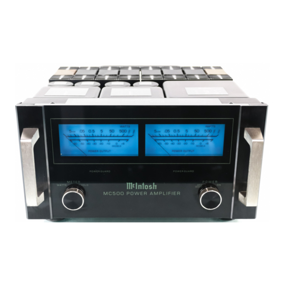
- Page 15 TRUE POWER OUTPUT WATT METERS TECHNICAL Two illuminated 5-1/2 inch WATT meters are provided on the MC500 front panel. The meters DESCRIPTION are peak responding and their circuits are constantly reading both voltage and current delivered to the loudspeaker loads. The load impedance of a loudspeaker may differ at various parts of the audio frequency range, resulting in a change of output current requirements.
-
Page 16: Specifications
POWER OUTPUT INTERMODULATION DISTORTION, SPECIFICATIONS SMPTE 500 watts per channel into an 8, 4 or 2 ohm load is the minimum sine wave con- 0.005% maximum if instantaneous peak tinuous average power output power output does not exceed twice the out- 1000 watts Mono into a 16, 8 or 4 ohm put rating load is the minimum sine wave continuous... - Page 18 04043200...
Need help?
Do you have a question about the MC500 and is the answer not in the manual?
Questions and answers