Table of Contents
Advertisement
Quick Links
Performance Specifications ........................................ 2
Notes ......................................................................... 2
Top and Rear Views ................................................... 3
Section Location ........................................................ 4
Block Diagram ...................................................... 5 - 6
Interconnection Diagram ...................................... 7 - 8
Driver/Heatsink Schematic and PCB ................... 9 - 13
POWER AMPLIFIER
CONTENTS
SERVICE MANUAL
Power Schematic and PCB ................................ 15 - 16
Input Schematic and PCB .................................. 17 - 18
Meter/Lighting Schematic and PCB .................... 19 - 20
Parts List ............................................................ 21 - 24
Exploded View and Parts List ............................. 25 - 28
Repacking Instructions ............................................. 29
Advertisement
Table of Contents

Subscribe to Our Youtube Channel
Related Manuals for McIntosh MC501


Summary of Contents for McIntosh MC501
-
Page 1: Table Of Contents
POWER AMPLIFIER CONTENTS Performance Specifications ........2 Power Schematic and PCB ........ 15 - 16 Notes ................. 2 Input Schematic and PCB ........17 - 18 Top and Rear Views ........... 3 Meter/Lighting Schematic and PCB ....19 - 20 Section Location ............ -
Page 2: Performance Specifications
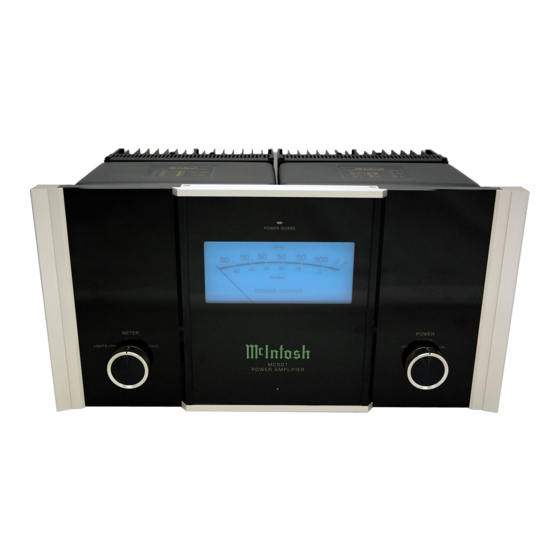
240 Volts, 50/60Hz at 3.3 amps Maximum Intermodulation Distortion if instantaneous peak output per channel does not exceed twice the rated output, Note: Refer to the rear panel of the MC501 for the for any combination of frequencies from 20Hz to 20,000Hz, correct voltage. - Page 3 MC501 TOP and REAR PANEL TOP VIEW REAR VIEW...
-
Page 4: Section Location
SECTION LOCATIONS TOP VIEW WITH COVER REMOVED BOTTOM VIEW WITH COVER REMOVED... -
Page 5: Block Diagram
MC501 BLOCK DIAGRAM... - Page 6 INTERCONNECT...
- Page 7 MC501 DRIVER/HEATSINK 049828 DRIVER SECTION...
- Page 8 DRIVER/HEATSINK 2A 2B 049828 HEATSINK SECTION...
- Page 9 MC501 DRIVER/HEATSINK NOTES 2A 2B 049828...
- Page 10 POWER 049831...
- Page 11 MC501 INPUT 049829...
- Page 12 METER/LIGHTING 049830...
-
Page 13: Parts List
MC501 PARTS LIST Ref. No. Description Part No. INTERCONNECT BINDING POST, RED 117740 BLADE FASTON W/FEET 117708 RES MF 1K 1% 1/4W 144090 BINDING POST, BLK 117741 CONN 4 PIN 117215 RES MF 221 OHM 1% 1/4W 144172 BINDING POST, RED 117740 BLADE FASTON .110... - Page 14 PARTS LIST con’t CAP ELECT 10UF 50V 066445 DIODE RECTIFIER 070131 LED GREEN 5MM HI-INT VF[V] 3.5 058165 CAP MONO .1uF 50V 20% Z5U 061305 LED GREEN 5MM HI-INT VF[V] 3.5 058165 DIODE RECTIFIER 070131 CAP MONO 47PF 200V 10% NPO 061299 DIODE SILICON 070047...
- Page 15 MC501 EXPLODED VIEW...
-
Page 16: Exploded View And Parts List
EXPLODED VIEW con’t and PARTS LIST 021159 BUSHING SWITCH 104138 WASHER FIBER .150ID X .312OD 102045 KEP NUT 6-32 SPECIAL 021030 SPACER 6 X 1/4 049830 ASSY METER PCB 101054 SCREW TAPTITE 6-32 X 1/4 PH PN BLK 101172 SCREW TC 6-32 X 1/4 PH FL U/C 005291 DUST COVER 100200... -
Page 17: Repacking Instructions
MC501 REPACKING INSTRUCTIONS... - Page 18 SERVICE MANUAL The continuous improvement of its products is the policy of McIntosh Laboratory Incorporated, who reserve the right to improve design without notice. Because of the constant upgrading of McIntosh products’ circuitry and components, the Company cannot insure, and does not warrant, the accuracy of the within schematic material, which is intended for information only.
Need help?
Do you have a question about the MC501 and is the answer not in the manual?
Questions and answers