
Related Manuals for McIntosh MC601


Summary of Contents for McIntosh MC601
-
Page 1: Power Amplifier
McIntosh Laboratory, Inc. 2 Chambers Street Binghamton, New York 13903-2699 Phone: 607-723-3512 www.mcintoshlabs.com MC601 Quad Balanced Power Amplifier Owner’s Manual... -
Page 2: Safety Instructions
The lightning flash with arrowhead, within an equilateral The exclamation point within an equilateral triangle is triangle, is intended to alert the user to the presence of intended to alert the user to the presence of important uninsulated “dangerous voltage” within the product’s en- operating and maintenance (servicing) instructions in the closure that may be of sufficient magnitude to constitute literature accompanying the appliance. -
Page 3: Table Of Contents
Dimensions ..............5 Dealer Name: ________________________________ it to the McIntosh MC601. Installation ..............6 In the event the MC601 over heats, due to improper Technical Assistance Rear Panel Connections and Switch ......7 ventilation and/or high ambient temperature, the Output Terminals and How to Connect ....8-9 If at any time you have questions about your McIntosh protection circuits will activate. -
Page 4: Connector And Cable Information
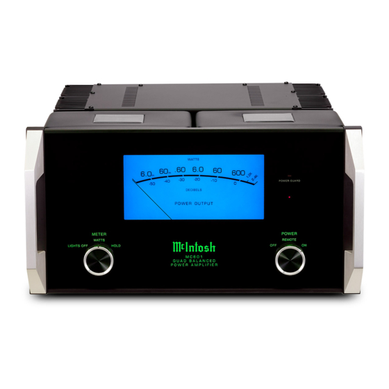
• Power Output trouble free operating life. Built-in Thermal Protection XLR Connectors The MC601 is a Power Amplifier with a capability of Circuits guard against overheating. Below is the Pin configuration for the XLR Balanced 600 watts into 2, 4 or 8 ohm speakers with less than Input, Input/Output Connectors on the MC601. -
Page 5: Dimensions
Dimensions Dimensions The following dimensions can assist in determining the best location for your MC601. Front View of the MC601 " 44.45cm " Side View of the MC601 " 7/16 22.54cm 23.97cm " 3/16 51.27cm " 15/16 45.55cm Rear View of the MC601 "... -
Page 6: Installation
Installation Installation 17" The MC601 can be placed upright on a table or 43.18cm shelf, standing on its four feet. It also can be custom installed in a piece of furniture or cabinet of your Opening for Ventilation choice. The four feet may be removed from the bottom of the MC601 when it is custom installed as outlined below. -
Page 7: Rear Panel Connections And Switch
2 ohm Loudspeaker cord to a live AC outlet. Refer to the rear panel to determine the correct voltage Caution: The Loudspeaker Negative Connections are above chassis ground. Do not combine any connections together, ground them or connect with another MC601. -
Page 8: How To Connect
3. Using a suitable tool remove the two screws from the Loudspeaker Cable Connec- Carefully remove sufficient insulation from the the MC601 Rear Panel and temporarily place them tion. Do not over tighten. Refer cable ends, refer to figures 2, 3 & 4. If the cable in a safe place. -
Page 9: Output Terminals And How To Connect
MC601 Rear Panel with the previously removed Cover Screws Screws. Refer to figure 5. Figure 5 (Inside USA and Canada) 10. Connect the MC601 power cord to an active AC 6. Attach the previously prepared bare outlet. Figure 7 Figure 8... -
Page 10: Output Terminals And How To Connect For Bi-Amp
5. Using a suitable tool remove the two screws from How to Connect for Bi-Amp the MC601 Rear Panel and temporarily place them Caution: Do not connect the AC Power Cord to the in a safe place. Refer to figure 1. -
Page 11: For Bi-Amp
MC601 Rear Panel with the previously removed Cover Screws Screws. Refer to figure 5. Figure 5 (Inside USA and Canada) 10. Connect the MC601 power cord to an active AC 6. Attach the previously prepared bare outlet. Figure 7 Figure 8... -
Page 12: Front Panel Displays And Controls
Front Panel Displays and Controls LED indicates when the Amplifier POWER GUARD circuit activates Meter indicates the Output Standby Power of the amplifier On Indicator METER Switch selects POWER Switch Turns AC Power Off, the display modes of the Remote, AC Power On Power Output Meter and Meter Illumination... -
Page 13: How To Operate
How to Operate Power On Input Mode Switch To have the MC601 automatically turn On or Off The Input Mode Switch, which is located on the Rear when a control center turns on or off, rotate the power Panel of the MC601, allows selection of either the switch to the Remote position. -
Page 14: Technical Description
The distortion limits for amplifier. The typical McIntosh owner would never mise, using the most advanced McIntosh circuit design the MC601 are no more than 0.005% at rated power accept the approximately 100 times higher distortion concepts. - Page 15 The high efficiency circuit design of the MC601 results in extra heat contributes to low operating temperatures. More than being generated in 1400 square inches of heat sink area keep the MC601 the power output operating safely with convection cooling. No fans are stage. This increase needed.
- Page 16 Power Output Meter ing conditions. The Under normal operating Without Power Guard The McIntosh MC601 has a large Output Watt Me- different types of conditions, there are no ter that responds 95% full scale to a single cycle tone protection circuits differences between the burst at 2kHz.
- Page 17 Figure 22 Figure 25 When the A/V Control Center is switched On, a (+5V) signal operates the power relay in the MC601. The MC601 also has two remote Power Control Out Jacks. The Power Control signal from these jacks are delayed...
-
Page 18: Specifications
Rated Power Band 22,000 ohms Balanced Standby: less than 0.5 watt 20Hz to 20,000Hz 22,000 ohms Unbalanced Note: Refer to the rear panel of the MC601 for the cor- rect voltage. Total Harmonic Distortion Voltage Gain Overall Dimensions 0.005% maximum harmonic distortion at any power 29dB, 8 Ohms Width is 17-1/2 inches (44.45cm) -
Page 19: Packing Instruction
If a shipping carton or any of the interior part(s) are needed, please call or write Customer Service Depart- ment of McIntosh Laboratory. Refer to page 3. Please see the Part List for the correct part numbers. Quantity... - Page 20 McIntosh Laboratory, Inc. 2 Chambers Street Binghamton, NY 13903 www.mcintoshlabs.com The continuous improvement of its products is the policy of McIntosh Laboratory Incorporated who reserve the right to improve design without notice. Printed in the U.S.A. McIntosh Part No. 04124501...
Need help?
Do you have a question about the MC601 and is the answer not in the manual?
Questions and answers