
Related Manuals for McIntosh MC257


Summary of Contents for McIntosh MC257
-
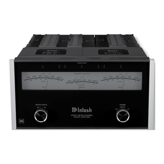
Page 1: Power Amplifier
McIntosh Laboratory, Inc. 2 Chambers Street Binghamton, New York 13903-2699 Phone: 607-723-3512 www.mcintoshlabs.com MC257 Power Amplifier Owner’s Manual... -
Page 2: Table Of Contents
Technical Assistance and Customer Service ....2 Purchase Date: _______________________________ it to the McIntosh MC257. Table of Contents ............2 In the event the MC257 over heats, due to improper General Information ........... 2 Dealer Name: ________________________________ ventilation and/or high ambient temperature, the Connector and Cable Information ......3... -
Page 3: Connector And Cable Information
Output Terminal Connector Music Playback in a second room with 160 watts per ish ensures the pristine beauty of the MC257 will be When cables with spade lugs are used channel, while at the time Zone A provides Five Chan- retained for many years. -
Page 4: Dimensions
Dimensions Dimensions The following dimensions can assist in determining the best location for your MC257. Front View of the MC257 " 44.5cm " " 7/16 22.5cm Side View of the MC257 24.0cm 1/4" 46.4cm " 42.2cm Rear View of the MC257 "... -
Page 5: Installation
Installation Installation 17" The MC257 can be placed upright on a table or 43.18cm shelf, standing on its four feet. It also can be custom installed in a piece of furniture or cabinet of your choice. The four feet may be removed from the bottom... -
Page 6: Rear Panel Connections And Switch
(Zone B) sends a turn On/Off Connection for the Connection for the Right Connection for the Cen- Connection for the Left Off signal from a McIntosh signal to the next McIntosh Right Front Channel Surround Channel and the ter Channel and the Right... -
Page 7: Output Terminals And How To Connect
Figure D Wrench over the top of the Out- Notes: 1. If desired, the twisted ends can be tinned 3. The MC257 has connections for Balanced Audio with solder to keep the strands together. put Terminal and rotate it one XLR Connection Cables that come from the con- 2. - Page 8 Place the the available connections, use the nearest lower LOAD Switch on the rear panel of the MC257 to impedance connection. Refer to “General Informa- either the 4 or 8 Ohm Setting, to match the imped- tion”...
-
Page 10: Front Panel Displays And Controls
Front Panel Displays and Controls Meter indicates the Front Meter indicates the Front The LEDs indicate when the POWER Meter indicates the Front Left Channel Output of Center Channel Output GUARD Circuitry has activated for the Right Channel Output of the amplifier of the amplifier Amplifier Center Channel (C4) -
Page 11: How To Operate
Rotate the METER LIGHTS Switch to the ON posi- To switch the MC257 OFF, place the Figure 10 use of the MC257, place the AUTO OFF Switch in the tion to Illuminate the three Front Panel Meters for the POWER Control in the OFF position. -
Page 12: Technical Description
25 amperes per channel; making this one of the most advanced amplifiers available today. The distortion limits for the MC257 are no more than 0.005% at rated power output for all frequencies from 20Hz to 20,000Hz. Typical performance at mid frequencies is less than 0.002%. - Page 13 2800 square inches of heat sink area keep the MC257 then drops. It is almost 10 times faster than a profes- as ThermalTrak™. Refer to figure operating safely with convection cooling.
- Page 14 Protection Circuits The Power Guard Without Power Guard circuit is a waveform To compliment the design of the MC257 Power Am- The MC257 incorporates the McIntosh Sentry Moni- tor Output Transistor Protection Circuit. Refer to comparator, monitoring plifier Circuitry, there is a high current high voltage both the input and output power supply.
- Page 15 McIntosh A/V Control Center. When the A/V Control Center is switched On, a (+5V) signal operates the power relay in the MC257. The MC257 also has two remote Power Control Out Jacks. The Power Control signal from these jacks is delayed by a fraction of a second so that the turn on power surge of the next power amplifier occurs at a later time.
-
Page 17: Photos
Photos... -
Page 18: Specifications
240 Volts, 50/60Hz at 6.5 Amps 8 and 4 ohms Greater than 140 at 8 ohms Standby: less than 0.5 watt Note: Refer to the rear panel of the MC257 for the cor- rect voltage. Rated Power Band Input Impedance... -
Page 19: Packing Instruction
Customer Service Depart- ment of McIntosh Laboratory. Refer to page 2. Please see the Part List for the correct part numbers. Quantity Part Number Description... - Page 20 McIntosh Laboratory, Inc. 2 Chambers Street Binghamton, NY 13903 www.mcintoshlabs.com The continuous improvement of its products is the policy of McIntosh Laboratory Incorporated who reserve the right to improve design without notice. Printed in the U.S.A. McIntosh Part No. 24100501...
Need help?
Do you have a question about the MC257 and is the answer not in the manual?
Questions and answers