JVC KW-XC828 Service Manual
Cd/cassette receiver
Hide thumbs
Also See for KW-XC828:
- Instructions manual (44 pages) ,
- Service manual (98 pages) ,
- Installation & connection manual (4 pages)
Advertisement
Quick Links
Download this manual
See also:
Instruction Manual
SERVICE MANUAL
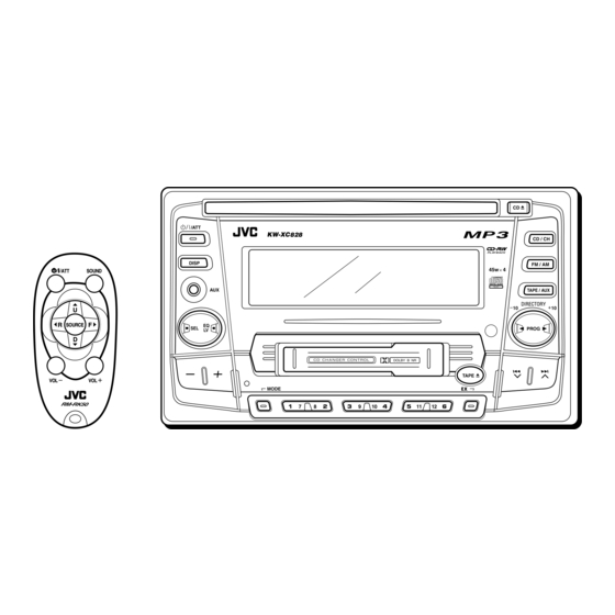
CD/CASSETTE RECEIVER
ATT
SOUND
U
R
SOURCE
F
D
VOL
VOL
Contents
Safety precaution
Disassembly method
Adjustment method
Flow of functional
operation unit TOC read
KW-XC828
1-2
1-3
1-30
1-31
COPYRIGHT
2002 VICTOR COMPANY OF JAPAN, LTD.
DIRECTORY
EX
U
Maintenance of laser pickup
Replacement of laser pickup
Description of major ICs
KW-XC828
Area Suffix
Ather Areas
1-33
1-33
1-36
No.49729
Apr. 2002
Advertisement

Related Manuals for JVC KW-XC828


Summary of Contents for JVC KW-XC828
- Page 1 KW-XC828 SERVICE MANUAL CD/CASSETTE RECEIVER KW-XC828 SOUND DIRECTORY SOURCE Area Suffix Ather Areas Contents Safety precaution Maintenance of laser pickup 1-33 Disassembly method Replacement of laser pickup 1-33 Adjustment method 1-30 Description of major ICs 1-36 Flow of functional operation unit TOC read 1-31 No.49729...
-
Page 2: Safety Precaution
KW-XC828 Safety precaution ! CAUTION Burrs formed during molding may be left over on some parts of the chassis. Therefore, pay attention to such burrs in the case of preforming repair of this system. ! CAUTION Please use enough caution not to see the beam directly or touch it in case of an... -
Page 3: Disassembly Method
KW-XC828 Disassembly method Joint a Removing the front panel assembly (See Fig.1 ~ 3) Remove the four screws A on both sides of the body. Release four joints a on both sides of the body using a screwdriver and remove the front panel assembly toward the front. - Page 4 KW-XC828 Removing the system control board / switch board (See Fig.4 , 5) System control board Prior to performing the following procedure, remove the front panel assembly. Remove the twelve screws B retaining the system control board. Remove the five screws C retaining the switch board.
- Page 5 KW-XC828 Removing the CD player section / cassette player section (See Fig.6 ~ 10) Prior to performing the following procedure, remove the front panel assembly. Remove the ten screws D, the screw E and F attaching the rear panel on the back of the body.
- Page 6 KW-XC828 <CD player section> Prior to performing the following procedure, remove Main board the front panel assembly, the CD player section and the cassette player section. Removing the main board (See Fig.11) CN601 Remove the three screws J attaching the main board.
- Page 7 KW-XC828 <Cassette player section> Main board CN972 Prior to performing the following procedures, remove the front panel assembly, the CD player section and the cassette player section. Removing the main board (See Fig.14) Disconnect the card wire from connector CN972 on the main board.
-
Page 8: Cd Mechanism Section
KW-XC828 < CD mechanism section > Removing the top cover (See Fig.1 and 2) Remove the two screws A on each side of the body. Top cover Joints a Lift the front side of the top cover and move the cover backward to release the two joints a. - Page 9 KW-XC828 Removing the DET switch (See Fig.3 and 6) Extend the two tabs c of the feed sw. holder and pull out the switch. DET switch Unsolder the DET switch wire if necessary. Connector board Removing the chassis unit (See Fig.7 and 8)
- Page 10 KW-XC828 Removing the clamper assembly (See Fig.9 and 10) Prior to performing the following procedure, remove Clamper arm the top cover. spring Remove the clamper arm spring. Move the clamper assembly in the direction of the arrow to release the two joints d.
- Page 11 KW-XC828 Feed sw. holder Removing the pickup unit (See Fig.13 to 17) Joint f Prior to performing the following procedure, remove the top cover, the connector board and the chassis unit. Remove the screw D and pull out the pu. shaft holder from the shaft.
- Page 12 KW-XC828 Removing the trigger arm (See Fig.18 and 19) Joint k Prior to performing the following procedure, remove the top cover, the connector board and the clamper unit. Trigger arm Turn the trigger arm in the direction of the arrow to release the joint k and pull out upward.
- Page 13 KW-XC828 Link plate Joint r Joint a' Removing the select arm (L) / select lock Select arm (L) Joint z Select arm (R) arm (See Fig.21 and 22) Select lock arm Prior to performing the following procedure, remove the top plate assembly.
- Page 14 KW-XC828 Joint a' Link plate Joint r Removing the select arm (R) / link plate Select arm (L) Joint z Select arm (R) (See Fig.21 and 22) Select lock arm Prior to performing the following procedure, remove the top plate assembly.
- Page 15 KW-XC828 Roller guide Removing the loading roller assembly Washer (See Fig.27 to 29) Loading roller assembly Prior to performing the following procedure, remove the clamper assembly and the top plate assembly. Roller guide Push inward the loading roller assembly on the gear side and detach it upward from the slot of the joint d’...
- Page 16 KW-XC828 Removing the loading gear (5), (6) and Loading gear bracket (7) (See Fig.31 and 32) Loading gear (6) Prior to performing the following procedure, remove the top cover, the chassis unit and the top plate assembly. Remove the screw J...
- Page 17 KW-XC828 Removing the gears (See Fig.33 to 36) Prior to performing the following procedure, remove the top cover, the chassis unit, the top plate assembly and the pickup unit. Slot j' Pull out the feed gear. Slide plate Loading plate assembly...
- Page 18 KW-XC828 Removing the turn table / spindle motor Turn table (See Fig.37 and 38) Prior to performing the following procedure, remove the top cover, the connector assembly and the chassis / clamper assembly. Remove the two screws K attaching the spindle motor assembly through the slot of the turn table on top of the body.
- Page 19 KW-XC828 REFERENCE: Prior performing following procedures, turn the mode gear on the bottom of the body until the respective part comes to the EJECT position (Refer to Fig.1). Removing the cassette guide (See Fig.2) Mode gear Turn the mode gear to set to RVS play or subsequent mode.
- Page 20 KW-XC828 Cassette holder assembly Removing the cassette hanger assembly / cassette holder (See Fig.4 to 7) Check the mode is set to EJECT. Push down the Boss d Side bracket Cassette hanger front part of the cassette holder and move in the assembly direction of the arrow to release the joint c.
- Page 21 KW-XC828 Removing the side bracket assembly Side bracket assembly (See Fig.8 to 10) Joint i Remove the screw A attaching the side bracket assembly. Joint j Detach the front side of the side bracket assembly upward and pull out forward to release the joint i and j in the rear.
- Page 22 KW-XC828 Removing the pinch arm (F) assembly (See Fig.11 and 12) Remove the polywasher and pull out the pinch arm (F) assembly. Remove the compulsion spring. Polywasher Pinch arm Polywasher Pinch arm (F) assembly (R) assembly Removing the pinch arm (R) assembly Fig.11...
- Page 23 KW-XC828 Removing the head / tape guide (See Fig.16 and 17) Slide chassis assembly REFERENCE: It is not necessary to remove the slide chassis assembly. Remove the band attaching the wire to the head. Remove the two screws B, the head and the head...
- Page 24 KW-XC828 Disassembling the flywheel assembly (F) (See Fig.20 and 21) Push and turn counterclockwise the spring holder (F) Flywheel assembly (F) Flywheel assembly (R) to release the three joints p on the bottom of the flywheel. The spring holder (F), the TU spring and the friction gear play come off.
- Page 25 KW-XC828 Removing the gear base arm / gear base Gear base arm Joint t link assembly (See Fig.25 to 27) Joints s Move the gear base arm in the direction of the arrow. Hook u Insert a slotted screwdriver to the gear base spring...
- Page 26 KW-XC828 Mode gear Mode switch actuator Removing the mode gear (See Fig.28 and 31) Remove the polywasher on the bottom and pull out the mode gear. Removing the mode switch actuator Polywasher (See Fig.28, 29 and 31) Pull out the mode switch actuator at the bottom.
- Page 27 KW-XC828 Slot e' Removing the gear base assembly / take up gear / reflector gear (See Fig.32 to 34) Push in the pin d’ of the gear base assembly on the upper side of the body and move the reflector gear toward the bottom, then pull out.
- Page 28 KW-XC828 Removing the side bracket assembly (See Fig.35 to 39) Remove the eject cam plate spring. Push the joint f‘ through the slot to remove the load rack downward. Joint f' Move the eject cam limiter in the direction of the arrow to release it from the boss g’...
- Page 29 KW-XC828 Main motor Removing the main motor assembly / assembly sub motor assembly (See Fig.40 to 42) Reduction gear (B) Belt Reduction Remove the belt at the bottom. gear (A) Polywasher Remove the polywasher and pull out the mode gear.
-
Page 30: Adjustment Method
Torque gauge Cassette for CTG-N(mechanism adjustment Laser power meter(Reader:LP800102) Frequency Range: Prove for MD (Reader:LP8010-02) FM: 87.5MHz to 108.0MHz Pre masterd disc (TGYS-1) AM: 531 kHz to 1602kHz Test disc (JVC:CTS1000) Cassette mechanism CN601 Extension cables EXTSH002-22P Main P.W.B CN501 CD mechanism... - Page 31 KW-XC828 Flow of functional operation unit TOC read Power ON When the laser diode correctly Set Function CD When the pickup correctly moves emits to the inner area of the disc Microprocessor $82 $81 Microprocessor Disc inserted commands commands 3.3V 3.3V...
- Page 32 KW-XC828 Feed section Is the voltage output at Is the wiring for IC521 Is 3.3V present at IC561 IC521 pin "40" 5V or 0V? (56)~(64) correct? pin "20"? Check CD 8V Check the vicinity of and 5V. IC521. Is 4V present at both...
- Page 33 KW-XC828 Maintenance of laser pickup (1) Cleaning the pickup lens Before you replace the pickup,please try to clean the lens with a alcohol soaked cotton swab. (2) Life of the laser diode When the life of the laser diode has expired.
- Page 34 KW-XC828 Mechanism Adjustment Section Item Adjust Std. Value Adjusting & Confirmation Methods "Head Height Adjustment" 1.Head azimuth Note Adjust the azimuth directly. When you adjust the height using a mirror tape, remove the cassette housing from the mechanism chassis. After installing the cassette housing, perform the azimuth adjustment.
- Page 35 KW-XC828 Arrangement of adjusting & test points Cassette mechanism (Surface) Azimuth screw (Reverse side) Head amplifier board Azimuth screw (Forward side) DOLBY NR Level Adj. Lch : VR401 Playback head DOLBY NR Level Adj. Rch : VR402 Capstan motor Tape speed adjust DOLBY NR Level Adj.
-
Page 36: Description Of Major Ics
KW-XC828 Description of major ICs BR24C01AFV-W-X (IC502) : EEPROM 1.Pin layout WPIN 2.Block diagram 1kbit EEPROM ARRAY 8bit 7bit SLAVE/WORD ADDRESS DATA WPIN 7bit DECODER ADDRESS REGISTER REGISTER START STOP CONTROL LOGIC HIGH VOLTAGE GEN. Vcc LEVEL DETECT 3.Pin function... - Page 37 KW-XC828 CXA2560Q (IC401) : Dolby B type noise reduction system with play back equalizer amp. 1.Pin layout & block diagram 7k/12k PBFB2 FF/REW 100k OFF/B PBRIN2 DIRECTION 300k MS MODE BIAS PBGND METAL MUTE PBFIN2 MUTE TAPE EQ NRSW NR MODE...
- Page 38 KW-XC828 UPD784215AGC173 (IC701) : Main micon 1.Pin layout 100 ~ 76 26 ~ 50 2.Pin functions(1/2) Pin No. Symbol Function Non connect Non connect Non connect MUTE Mute output terminal("L" output at mute) Connects with VDD Connects with X'tal departure pendulum of 12.5MHz(output )(main) Connects with X'tal departure pendulum of 12.5MHz(input )(main)
- Page 39 KW-XC828 2.Pin functions(2/2) UPD784215AGC173(2/2) Pin No. Symbol Function Non connect 44~47 Data input from EPROM EPROM DI Data output to EPROM EPROM DO EPROM Clock signal I/O EPROM CK SD/SI Stationdetector and stereo signal input terminal ("H" input at SD)
- Page 40 KW-XC828 UPD784225GK-623 (IC501) : CPU 1.Pin layout 2.Pin function Symbol Function Function Symbol Connect to TEMP detecter Non use TEMP Connect to GND Non use Connect to GND Non use Connect to GND DAC mode control latch AVSS DACML No use...
- Page 41 KW-XC828 UPD789166GB-590 (IC431) : CPU 1.Pin layout 44 ~ 34 12 ~ 22 2.Pin function Pin No. Symbol Function KEY0 KEY0 input terminal KEY1 KEY1 input terminal KEY2 KEY2 input terminal KEY SEL KEY in select setting terminal (H:active) DOLBY SEL...
- Page 42 KW-XC828 HA13164A (IC911) : Regulator 1.Terminal layout 1 2 3 4 5 6 7 8 9 10 11 12 13 14 15 2.Block diagram 100u 0.1u BATT.DET OUT ANT OUT Surge Protector 0.1u EXT OUT ACC 5V BIAS 0.1u VDD OUT ANT CTRL 0.1u...
- Page 43 KW-XC828 LC75878W (IC501) : LCD driver 1. Pin layout 100 ~ 76 26 ~ 50 2. Block diagram GENERAL COMMON SEGMENT DRIVER & LATCH PORT DRIVER CONTROL CLOCK GENERATOR REGISTER VLCD CONTRAST SHIFT REGISTER ADJUSTER VLCD0 VLCD1 VLCD2 INTERFACE VLCD3 VLCD4 3.
- Page 44 KW-XC828 LA4743K (IC901) : Power amp. 1.Block diagram 2200 F 0.022 F Vcc 1/2 Vcc 3/4 IN 1 OUT 1+ 0.22 F OUT 1- PWR GND1 Protective circuit OUT 2+ IN 2 OUT 2- 0.22 F PWR GND2 ST BY...
- Page 45 KW-XC828 2.Terminal layout 3.Pin function Pin No. Symbol Function Header of IC Power GND RFOUT- Outpur(-) for front Rch Stand by input STBY Output (+) for front Rch RFOUT+ Power input RROUT- Output (-) for rear Rch Power GND RROUT+...
- Page 46 KW-XC828 LA6579H-X (IC681) : 4-Channel bridge driver 1. Pin layout & Block diagram VIN1-A VIN1 VIN1_SW [H]: OP-AMP_A [L]: OP-AMP_B VIN1+A VIN1-B VCCP1 VIN1+B Signal system S-GND power supply VIN1-SW All outputs ON/OFF H : ON VO2+ MUTE MUTE L : OFF...
- Page 47 KW-XC828 3.Pin function Pin No. Symbol Function CH1 input AMP_inverted input VIN1-A CH1 input AMP_non-inverted input VIN1+A CH1 and CH2 power stage power supply VCCP1 Output pin(+)for channel 1 VO1+ CH1 output pin (-) for channel 1 VO1- Output pin(+)for channel 2...
- Page 48 KW-XC828 TA2157FN-X(IC601):RF amp 1.Terminal layout 2.Block diagram PEAK 50 A BOTTOM PEAK 1.75k 240k 15pF x0.5 240k 15pF x0.5 180k 40pF RFGC (APC SW) (TE BAL) (AGC Gian) (TE BAL) VCTRLPIN Normal mode APC ON -50% +12dB (0dB) Normal mode...
- Page 49 KW-XC828 3.Pin function TA2175FN-X Pin No. Symbol Function 3.3V power supply pin Main-beam amp input pin Main-beam amp input pin Sub-beam amp input pin Sub-beam amp input pin Monitor photo diode amp input pin Laser diode amp output pin APC circuit ON/OFF control signal, laser diode (LDO) control signal input or bottom/peak detection frequency change pin.
- Page 50 AD11 Interrupt General Flag SRAM I/F Timer Control Output Port AD12 I-Bus Address Calc. 2sets ERAM TESTP CROM XRAM YRAM 2k word 4k word 4k word 4k word VSSR Y-Pointer X-Pointer C-Pointer register register register Prog. VRAR Start X-Bus Switch Y-Bus register VDAR...
- Page 51 KW-XC828 3.Pin function(1/2) TC94A02F-005 Pin No. Symbol Function Hard reset input terminal(H:Normal operation L: Reset) /RESET Micon I/F mode select input terminal MiMD External SRAM address output 0 terminal External SRAM address output 1 terminal Micon I/F data input/output terminal...
- Page 52 KW-XC828 3.Pin function(2/2) TC94A02F-005 Pin No. Symbol Function External SRAM data input/output 4 terminal Digital power supply (2.5V) terminal External SRAM data input/output 5 terminal External SRAM data input/output 6 terminal External SRAM data input/output 7 terminal VSSP VCO GND...
- Page 53 KW-XC828 M61508FP-X (IC951) : E. volume 1. Pin layout & Block diagram LOUDNESS (Digital) (Anarog) 3BAND TONE CONTROL (BASS/MID/TREBLE) Soft select Z E R O C RO S S D E T E C T O R Z e r o d e t e c t...
- Page 54 KW-XC828 TC94A14FA (IC621) : DSP & DAC 1.Terminal layout & block daiagram Clock generator 1-bit Servo control Digital equalizer Address automatic circuit adjustment circuit Data CLV servo slicer 16 k Synchronous guarantee decoder Audio out Digital circuit output Micro- controller...
- Page 55 KW-XC828 TC94A14FA Symbol Description EFM and PLCK phase difference signal output pin. TMAX TMAX detection result output pin. TMAX Detection Result TMAX Output Longer than fixed period "PV " Within fixed period "HiZ" Shorter than fixed period "AV " LPFN Inverted input pin for PLL LPF amp.
- Page 56 KW-XC828 PCM1716E-X (IC571) : D/A converter 1. Pin layout 2. Block diagram Serial VoutL Low-pass Filter LBCK Input Mult-level EXTL 8X Oversampling DATA Delta-Sigma Digital Filter Low-pass VoutR Modulator Filter with ML/llS Function Controller EXTR MC/DM1 Mode MD/DM0 ZERO Control...
- Page 57 KW-XC828 TB2118F-X (IC21) : PLL 1.Terminal Layout 2.Block diagram Constant power supply voltage Buff. ON/OFF AM CP. Phase OSC circuit Reference Counter Comparator switch FM VCO 4-bit Prescaler Swallow counter 12-bit AMVCO Programmable counter REG. 20-bit BINARY COUNTER Resistor 1...
- Page 58 KW-XC828 HD74HCT126T-X (IC503) : Buffer 1.Terminal layout 3.Pin function OUTPUT INPUT H : High level L : Low level X : Irrelevant Off (Hhigh-impedance)state of a 3-stage output 2.Block diagram 1-58...
- Page 59 KW-XC828 BR24C16F-X (IC702) : EEPROM 1. Pin layout 2. Pin function WPIN Symbol I/O Function Power supply. A0,A1,A2 No use connect to GND. Serial clock input. Serial data I/O of slave and ward address. WPIN Write protect terminal. 3. Block diagram...
- Page 60 KW-XC828 HD74HC126FP-X (IC461,IC761) : Buffer 1.Pin layout 2.Pin function Input Output Note) H:High level L:Low level X:Irrelevant Z:Off(High-impedance) State a 3-state input 3.Block diagram Output Input Output Sample as Load Circuit 1 Output Sample as Load Circuit 1 Output Sample as Load Circuit 1...
- Page 61 KW-XC828 IC-PST9333U-X (IC432,IC791) : Regulator 1. Pin layout 2. Block diagram VOUT VOUT 3. Pin function Pin No. Symbol Function Non connect GND terminal VOUT Reset signal output terminal Vcc terminal/Voltage detect terminal RPM6938-V4 (IC502) : Remocon reseiver 1. Block diagram...
- Page 62 KW-XC828 W24L010AJ-12-X (IC653) : SRAM 1. Pin layout 2. Block diaglam DECODER CORE ARRAY I/O1 CONTROL DATA I/O I/O8 3. Pin function Pin No. Symbol Function Pin No. Symbol Function No Connection I/O4 Data Input/Output Address Input I/O5 Data Input/Output...
- Page 63 KW-XC828 VICTOR COMPANY OF JAPAN, LIMITED MOBILE ELECTRONICS DIVISION PERSONAL & MOBILE NETWORK BUSINESS UNIT. 10-1,1Chome,Ohwatari-machi,Maebashi-city,371-8543,Japan 200204 (No.49729)
-
Page 64: Block Diagram
KW-XC828 Block diagram OUTLF INLF IC901 OUTRF INLR IC951 TU.L,TU.R FM/AM POWER OUTFR INRF E.VOL FRONTL TUNER OUTRR VA,VB IC601 RWSEL IC571 VOUTL IC572 INRR REARL VE,VF VOUTR CD RF 24bit DAC CD LPF SEEK/STOP FRONTR MD,LD SD/ST REARR DACML CD.L-CH... -
Page 65: Standard Schematic Diagrams
KW-XC828 KW-XC828 Standard schematic diagrams Receiver & System control section QAU0258-001 C291 CH-Rch R291 4.7k IC951 1/50 M61508FP-X TAPE-Rch C272 1/50 C201 R221 C248 2.2/50 IC901 CD-Rch R241 2.7K C242 1/50 C249 2.2/50 1/50 LA4743K TU-Rch C202 R222 C281 AUXR... - Page 66 KW-XC828 LCD driver & Operation switch section CN702 CN973 QGF1016F3-21 CN972 QGF1016F3-21 QGF1016F3-15 L942 L941 TAPE-Lch TAPE-Rch VDD5V CH-Lch GNDM CH-Rch CD-Lch R975 Q941 CD-Rch Q943 UN2211-X CD8V UN2213-X MOUT CN971 CN601 ROUT QNZ0095-001 QGB2027M4-22S SI/SO CDREQ L804 ON5V MEMORY...
- Page 67 KW-XC828 KW-XC828 Mecha control circuit section IC402 LB1641 CN403 QGF1219F1-10 C425 0.01 Q403 2SB1322/RS/-T C424 R424 R425 2.2k R426 Q402 R401 DTC114EKA-X R448 IC432 R417 IC-PST9333U-X R420 120k Q401 R443 X431 C411 2.2K 0.015 R450 R449 C461 0.01 R466 CJ402...
- Page 68 KW-XC828 CD servo control section RWSEL R585 C589 C587 4.7/35 C585 120P R613 R581 C611 R583 R611 R610 CD.L-CH 4.7/35 R614 R612 C610 C586 R582 C588 R584 CD.R-CH 120P C590 4.7/35 Q571 R586 4.7/35 ON5V UN2111 X571 R601 R607 R602...
- Page 69 KW-XC828 KW-XC828 Printed circuit boards Main board (Reverse side) Main board (Forward side) IC911 CN911 C131 CN951 C232 D913 D933 IC911 R161 R261 R162 R262 R926 R291 CN702 R927 C916 L911 CN951 D911 CN911 CN702 C915 C925 R914 C919 C917...
- Page 70 KW-XC828 Front board (Forward side) D522 S533 D561 D562 D521 D529 D530 S511 S501 D524 D532 D531 S521 S502 D533 D534 S503 LCD1 D525 D526 D535 D536 D537 D538 D527 D528 D583 D576 S536 D575 D581 D569 D570 D571 D572...
- Page 71 KW-XC828 Front board (Reverse side) R590 R589 R592 R588 R593 R591 R587 R599 R554 R598 R540 R539 R595 R510 R556 R528 R537 R527 R538 R594 R553 R546 Q502 R545 R536 CN501 R544 R535 R534 C511 R552 R533 R543 R516 R542...
- Page 72 KW-XC828 PARTS LIST [ KW-XC828 ] * All printed circuit boards and its assemblies are not available as service parts. Area suffix U --------------------- Other Areas - Contents - 3- 2 Exploded view of general assembly and parts list (Block No.M1) 3- 5 CD mechanism assembly and parts list (Block No.MB)
- Page 73 KW-XC828 Exploded view of general assembly and parts list Block No.
- Page 74 KW-XC828 Parts list (General assembly) Block No. M1MM Item Parts number Parts name Q'ty Description Area --------------- CD MECHA 1 TN-2001-1003 QYSDST2004Z SCREW VYSH101-009 SPACER --------------- CASSETTE MECHA 1 CDS-802JE3 LV21157-001A MECHA BKT(CA) QYSDST2604Z SCREW 1 PWB+CS BKT QYSDST2604Z SCREW...
- Page 75 KW-XC828 Parts list (General assembly) Block No. M1MM Item Parts number Parts name Q'ty Description Area QUQ210-2107CJ FFC WIRE FFC WIRE QUQ210-1512CJ VMA4652-001SS EARTH PLATE LV42302-001A POWER IC BRACKE LV42670-001A REG.IC BRACKET FUSE QMFZ047-150-T LV33136-001A LIGHTING CASE LV33137-001A LCD CASE...
- Page 76 KW-XC828 CD mechanism assembly and parts list Block No. TN-2001-1003 Grease TNG-87...
- Page 77 KW-XC828 Parts list (CD mechanism) Block No. MBMM Item Parts number Parts name Q'ty Description Area 30320101T FRAME 30320102T TOP COVER 30320109T DAMPER F 30320110T DAMPER R 303205501T CHASSIS RIVET A 303205503T CHANGE P.RVT A 303205301T CLAMPER ASS'Y 303205304T SPINDLE MOTOR A...
- Page 78 KW-XC828 Parts list (CD mechanism) Block No. MBMM Item Description Parts number Parts name Q'ty Area 30321103T LOADING GEAR 3 30321104T LOADING GEAR 4 LOADING GEAR 5 30321105T 30321106T LOADING GEAR 6 30321107T LOADING GEAR 7 30321111T ROLLER GUIDE 30321114T...
- Page 79 KW-XC828 Cassette mechanism assembly and parts list Block No. CDS-802JE3...
- Page 80 KW-XC828 Parts list (Cassette mechanism) Block No. MPMM Item Parts number Parts name Q'ty Description Area X-0802-1009S MAIN CHASSIS AS X-0802-1002S SLIDE CHASSIS A X-0802-1003S SIDE BKT ASSY X-0802-1004S CASSETTE HANGER X-0802-1005S PINCH ARM(F)ASS X-0802-1006S PINCH ARM(R)ASS X-0802-1007S GEAR BASE LINK...
- Page 81 KW-XC828 Parts list (Cassette mechanism) Block No. MPMM Item Description Parts number Parts name Q'ty Area 1-0802-4008S REEL DRIVER SPG 1-0802-4013S COMPULSION SPG BELT 1-0802-5001S 1-0802-5002S FELT 1 7.5*18.5*1 1-0802-5003S AZIMUTH SCREW 1-0802-5004S FELT 1 11*18.5*1 1-0050-5023S WTRE CLAMPER 1-0802-7001S...
- Page 82 KW-XC828 Grease point 1/2 FG-84M MEA-512R MEN-223 SW-902 CFD-409 CFD-250H EP-56 SW-474B 3-11...
- Page 83 KW-XC828 Grease point 2/2 3-12...
- Page 84 KW-XC828 Electrical parts list (Main board) Block No. 01 Item Parts number Parts name Remarks Area Item Parts number Parts name Remarks Area NCB31HK-103X C CAPACITOR C 248 QERF1HM-225Z E CAPACITOR 2.2MF 20% 50V NCB31HK-103X C CAPACITOR C 249 QERF1HM-225Z E CAPACITOR 2.2MF 20% 50V...
- Page 85 KW-XC828 Electrical parts list (Main board) Block No. 01 Item Parts number Parts name Remarks Area Item Parts number Parts name Remarks Area C 992 NCS31HJ-101X C CAPACITOR UN2211-X TRANSISTOR C 993 NCS31HJ-101X C CAPACITOR Q 81 2SD601A/RS/-X TRANSISTOR C 994...
- Page 86 KW-XC828 Electrical parts list (Main board) Block No. 01 Item Parts number Parts name Remarks Area Item Parts number Parts name Remarks Area R 141 NRSA63J-272X MG RESISTOR R 746 NRSA63J-473X MG RESISTOR R 142 NRSA63J-123X MG RESISTOR R 752...
- Page 87 KW-XC828 Electrical parts list (Front board) Block No. 02 Item Parts number Parts name Remarks Area Item Parts number Parts name Remarks Area C 501 NBE21AM-106X E CAPACITOR R 518 NRSA63J-222X MG RESISTOR C 502 NBE21AM-106X E CAPACITOR R 520...
- Page 88 KW-XC828 Block No. 02 Electrical parts list (Front board) Item Remarks Parts number Parts name Area S 501 NSW0066-001X TACT SWITCH S 502 NSW0066-001X TACT SWITCH S 503 NSW0066-001X TACT SWITCH S 504 NSW0066-001X TACT SWITCH S 505 NSW0066-001X TACT SWITCH...
- Page 89 KW-XC828 Electrical parts list (CD mecha control board) Block No. 03 Item Parts number Parts name Remarks Area Item Parts number Parts name Remarks Area C 501 NCB31HK-103X C CAPACITOR C 628 NEAD0JM-476X E CAPACITOR C 502 NCB31HK-103X C CAPACITOR...
- Page 90 KW-XC828 Electrical parts list (CD mecha control board) Block No. 03 Item Parts number Parts name Remarks Area Item Parts number Parts name Remarks Area IC504 NJU7241F33-X R 542 NRSA63J-101X MG RESISTOR IC571 PCM1716E-X R 543 NRSA63J-0R0X MG RESISTOR IC572...
- Page 91 KW-XC828 Electrical parts list (CD mecha control board) Block No. 03 Item Remarks Parts number Parts name Area R 626 NRSA63J-474X MG RESISTOR R 627 NRSA63J-103X MG RESISTOR R 628 NRSA63J-225X MG RESISTOR R 629 NRSA63J-103X MG RESISTOR R 630...
- Page 92 KW-XC828 Electrical parts list (Mecha control board) Block No. 04 Item Parts number Parts name Remarks Area Item Parts number Parts name Remarks Area C 401 NCS31HJ-101X C CAPACITOR R 420 NRSA63J-124X MG RESISTOR C 402 NCS31HJ-101X C CAPACITOR R 421...
- Page 93 KW-XC828 Packing materials and accessories parts list Block No. Block No. A1~A4 A5, A6 3-22...
- Page 94 KW-XC828 Parts list (Packing) Block No. M3MM Item Description Parts number Parts name Q'ty Area QPA01703505P POLY BAG 1 INST.BOOK QPA00801205 POLY BAG 1 SCREW ASSY QPC03004315P POLY BAG 1 SET LV33415-001A CARTON LV10614-001A CUSHION LV10615-001A CUSHION Parts list (Accessories) Block No.
Need help?
Do you have a question about the KW-XC828 and is the answer not in the manual?
Questions and answers