Table of Contents
Advertisement
Quick Links
Maas
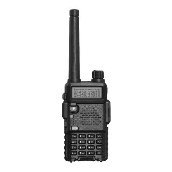
AHT-28-V/AHT-78-U
Handheld Transceivers
User's Manual
Thank you very much for using our two way radio.
This radio of modern design is reasonable structure
with stable functions. It is designed to meet different
customers' need for high quality with easy operation
and perfect capablity. We believe you are pleased with
its nice shape and excellent performance.
This manual is suitable for using the model of
AHT-28-V/AHT-78-U .
Advertisement
Table of Contents

Subscribe to Our Youtube Channel
Related Manuals for Maas AHT-28-V


Summary of Contents for Maas AHT-28-V
- Page 1 It is designed to meet different customers' need for high quality with easy operation and perfect capablity. We believe you are pleased with its nice shape and excellent performance. This manual is suitable for using the model of AHT-28-V/AHT-78-U .
- Page 2 Welcome to use two-way radio www.maas-elektronik.com...
-
Page 3: Main Functions
Main Functions Single band, dual display, dual standby A/B band independent operation 2x128 channels storage and scanning FM radio and 25 stations memory www.maas-elektronik.com Wide/Narrow band selectable VOX 0~9 grade setting Chinese/English voice prompt CTCSS/DCS and scanning 1750Hz tone ANI function... -
Page 4: Table Of Contents
CONTENTS USING TIPS UNPACKING AND CHECKING EQUIPMENT Supplied Items CHARGING BATTERY PACK Charging Preparation Charging Operation INSTALLATION OF ACCESSORIES Installation of Battery Pack Antenna Installation Installing Belt Clip Installing External Micro/Speaker Wrist Strap Installation GETTING FAMILIAR Radio Illustration LCD Display Keypad Functions MODEL VERSION WORKING MODE... - Page 5 Reset Mode SET MENU MODE SHORTCUT MENU OPERATION DETAILED FUNCTION DESCRIPTION Scan & Scan Mode setting Priority Transmit VOX Level & VOX Switch TX Power setting Squelch Adjustment Dual Wait/Standby LED Display Mode Background Light Color Keypad Beeper setting Automatic Number Identity Transmitter Time-Out Timer Busy Channel Lock-Out Transmit Over Beeper...
- Page 6 Tone coder & Tone Search Scanning & Tone calling VFO Step setting Wide/Narrow Band Selecting Voice Mode and Scrambler ADVANCED FUNCTIONS PTT ID setting Emergency Alert Keypad Lock setting Reverse Frequency Tone Calling (1750Hz) Channel Storage/Delete FM Radio Function Wire Clone OPTIONAL SIGNALINGS DTMF Part MSK Part...
- Page 7 User's Manual USING TIPS UNPACKING AND CHECKING EQUIPMENT www.maas-elektronik.com...
-
Page 8: Using Tips
USING TIPS Please read the following brief instructions, non-compliance with these rules may cause danger or violate the law. Obey the local government regulation before using this radio, improper use may violate the law and be punished. Turn off the radio before entering flammable or explosive areas. Do not charge or change the battery in flammable or explosive areas. -
Page 9: Unpacking And Checking Equipment
UNPACKING AND CHECKING EQUIPMENT to use AHT-28-V/AHT-78-U. Supplied Items: Transceiver (1) - Page 10 User's Manual CHARGING BATTERY PACK INSTALLATION OF ACCESSORIES www.maas-elektronik.com...
-
Page 11: Charging Battery Pack
CHARGING BATTERY PACK Charging Precaution 7.4V 1600... -
Page 12: Charging Operation
Charging Operation Indicator Display Status Green... -
Page 13: Installation Of Accessories
INSTALLATION OF ACCESSORIES Installation of Battery Pack Fit the supplied battery pack into the batter pack trough, then slide it toward the head to insert it completely---in direction of arrowhead (Picture 1). Push the battery pack lock to release the battery pack and slide it toward the bottom to remove it out---in direction of arrowhead (Picture 2). -
Page 14: Antenna Installation
Antenna Installation Picture 3 Picture 4 C A L L C A L L M O N M O N A / B A / B V O X V O X P R I P R I S C A N S C A N S Q L S Q L... -
Page 15: Installing Belt Clip
Installing Belt Clip P U S P U S Picture 5 Picture 6... -
Page 16: Installing External Micro/Speaker
Installing External Micro/Speaker A /B SC AN P R I V O X PW R S Q L LE D CO LO R BE EP LO CK FM RA DIO A N I T - R EX IT Picture 7 Wrist Strap Installation P U S Picture 8... -
Page 17: Getting Familiar
User's Manual GETTING FAMILIAR www.maas-elektronik.com... -
Page 18: Radio Illustration
RADIO ILLUSTRATION POWER/VOLUME DIAL This control toggle the ANTENNA transceiver’s power on/off and Connect the supplied adjust the audio volume level. antenna here. BUSY/TX SPEAKER The indicator turns green The internal speaker is during receive and turns located here. red during transmit/ emergency alarm. - Page 19 CALL Activates T-CALL (1750Hz) for repeater access and transmit DTMF and 2/5 tone signaling. CALL MIC/SP The jack provides connection Press it to transmit and release points for microphone audio, it to receive after your earphone audio, speaker and transmission is completed. MONI program cable.
-
Page 20: Lcd Display
LCD DISPLAY You will see various icons shown on the screen when power on. The following table can help you identify icons’ meaning which display on LCD. Icons Description of functions Operating band signal & power meter Low TX power active Dual watch/standby active RX power save active VOX active... - Page 21 Icons Description of functions Squelch active Beep tone active Receive calling ID or MSG Scrambler active Battery power indicator CTCSS decoder active DCS decoder active 5 Tone signaling active 2 Tone signaling active DTMF signaling active Operating A band indicator Operating B band indicator Frequency mantissa indicator Channel number/Menu items number indicator...
-
Page 22: Keypad Functions
KEYPAD FUNCTIONS Press Enter menu Switch the Upper menu Lower menu Switch VFO mode/confirm A or B item, channel item, channel mode and the setting frequency or frequency or frequency MR mode/exit to be the the setting “Operating” Band Press and Enter reset No action Switch CH... - Page 23 Press Frequency/ Frequency/ Frequency/ Frequency/ Frequency/ Channel No. Channel No. Channel No. Channel No. Channel No. entry “6” entry “7” entry “8” entry “9” entry “0” Press Enter dual Enter LED Enter color Enter beep Enter ANI wait/standby item item item item item...
- Page 24 User's Manual MODEL VERSION WORKING MODE SET MENU MODE SHORTCUT MENU OPERATION www.maas-elektronik.com...
-
Page 25: Model Version
Only 2/5 TONE version will be with 8 groups of scrambler function. Please choose the right AHT-28-V/AHT-78-U model type when you use software to program it. If not, it will affect some functions operation. Detail please see picture as below:... -
Page 26: Working Mode
WORKING MODE 1) Frequency Mode (VFO) Under this mode, you can use [ ] / [ ] key to change the frequency or input the frequency by keypad directly and store channels. 2) Frequency-Channel Mode (MR) When you have stored a memory channel at least and under VFO mode, press [ key to enter MR mode. -
Page 27: Menu Mode
5) MENU Mode Press [ ] key to enter MENU mode, there are 34 items in total. Please see SET MENU MODE. Page 22 6) Reset Mode Press [ ] key and switch the power on to enter Reset mode, then press [ ] key to enter. -
Page 28: Set Menu Mode
SET MENU MODE LCD Display Available Values Description of Function SCAN Frequency/Channel Scan TX.SEL EDIT / BUSY Priority Transmit VOX Level Setting POWER LOW / HIGH High/Low TX Power SQL level setting D.WAIT ON / OFF Dual Wait/Standby ON / AUTO / OFF LED Display mode LIGHT COLOR1 / COLOR2 / COLOR3... - Page 29 LCD Display Available Values Description of Function RX.SAV ON / OFF Receive Saver Receive Saver SCAN.S TO / CO / SE Scan Mode Scan Mode AUTOLK ON / OFF Auto Keypad Lock Auto Keypad Lock VOICE ON / OFF Voice Prompt Voice Prompt OPNSET OFF / DC / MSG...
- Page 30 LCD Display Available Values Description of Function WIDE/NARROW Wide/Narrow Band SEEK 67.0 CTCSS Scanning SEEK D023N DCS Scanning Voice Scrambler SCR.NO (Only for 5T&2T version) Voice Mode APRO OFF / COMP / SCRA (Only for 5T&2T version) Menu Operation Under standby mode, press [ ] to enter menu setting, LCD displays “MENU”.
-
Page 31: Shortcut Menu Operation
SHORTCUT MENU OPERATION Item Item Enter Screen Select Parameter Confirm Return Name item Display parameter Explanation Standby Frequency Press [ ] or Press [ ] key to ] to change /Channel start scanning scan direction scan Priority Press [ ] or EDIT / BUSY ] to select Transmit... - Page 32 Item Item Enter Screen Select Parameter Confirm Return Name item Display parameter Explanation Standby Automatic Press [ ] or ] to select ON / OFF Number available values Identity Transmitter Press [ ] or OFF / 30... / 270s ] to select time-out available values timer...
- Page 33 Item Item Enter Screen Select Parameter Confirm Return Name item Display parameter Explanation Standby Voice Press [ ] or ON / OFF ] to select prompt available values Power-on Press [ ] or OFF / DC / MSG ] to select display available values Battery...
- Page 34 Item Item Enter Screen Select Parameter Confirm Return Name item Display parameter Explanation Standby RX tone Press [ ] or OFF / QT / DCS ] to select coder available values TX tone Press [ ] or OFF / QT / DCS ] to select coder available values...
- Page 35 User's Manual DETAILED FUNCTION DESCRIPTIONS ADVANCED FUNCTIONS www.maas-elektronik.com...
-
Page 36: Detailed Function Description
DETAILED FUNCTION DESCRIPTIONS 1) Scan & Scan Mode setting (SCAN&SCANS---MENU 1&17) Functions: under VFO/MR/CH mode, the transceiver allows you to scan the entire current operating band and memory channels. Enter Menu 1 and press [ ] key to start scanning. When you have started scanning, press [ ] / [ ] key to change direction. -
Page 37: Priority Transmit
2) Priority Transmit (TX.SEL---MENU 2) Functions: The AHT-28-V/AHT-78-U allows you to transmit on the sub band even if you are working on the operating band. Enter Menu 2 to select priority transmit band. Default: EDIT. EDIT: It will transmit on the operating band. -
Page 38: Tx Power Setting
SQL level. Default: 5. 6) Dual Wait/Standby (D.WAIT---MENU 6) Functions: The AHT-28-V/AHT-78-U allows you to receive the sub band signal even if you are working on the operating band. It could monitor the signal under both master and sub band at the same time. -
Page 39: Led Display Mode
7) LED Display Mode (LED---MENU 7) Function: select the LED/Keypad Lamp mode. Enter Menu 7 to select LED display mode. Default: AUTO. ON: LED display lights all the time. AUTO: Illuminates the LED when any key is pressed and after 3s the light is off. OFF: Disable the LED lamp. -
Page 40: Transmitter Time-Out Timer
11) Transmitter Time-Out Timer (TOT---MENU 11) Functions: the TOT feature provides a safety switch which limits transmission to a pre-programmed value. This will promote battery conservation by not allowing you to make excessively-long transmissions, and in the event of a stuck PTT switch it can prevent interference to other users as well as battery depletion. -
Page 41: Dual Watch/Monitor
14) Dual Watch/Monitor (DW---MENU 15) Functions: Dual Watch feature makes the transceiver can monitor the calling signal when FM radio is on and you won’t miss any calling. Enter Menu 15 to set DW. Default: OFF. 15) Receive Saver (RX.SAV---MENU 16) Functions: this feature significantly reduces quiescent battery drain, and you may not receive the full data burst. -
Page 42: Power-On Display Setting
18) Power-on Display setting (OPN.SET&VLT&PON.MSG---MENU 20&21&22) Functions: choose power-on display mode and edit power-on message Enter Menu 20 to set OPN.SET. Default: OFF. OFF: display model version DC: battery power voltage MSG: power-on message Enter Menu 21 to check battery voltage. Enter Menu 22 to edit power-on message, also you can edit it directly by program software. -
Page 43: Display Channel Name
20) Display Channel Name (DIS.NAME&CH.NAME---MENU 23&24) Functions: switch channel name display ON/OFF and edit channel name under MR/CH mode. Enter Menu 23 to switch display channel name ON/OFF. Enter Menu 24 to edit channel name, also you can edit it directly by program software. - Page 44 CTCSS TONE FREQUENCY (Hz) 67.0 69.3 71.9 74.4 77.0 79.7 8.25 85.4 88.5 91.5 94.8 97.4 100.0 103.5 107.2 110.9 114.8 118.8 123.0 127.3 131.8 136.5 141.3 146.2 151.4 156.7 159.8 162.2 165.5 167.9 171.3 173.8 177.3 179.9 183.5 186.2 189.9 192.8 196.6...
- Page 45 DCS CODE...
-
Page 46: Vfo Step Setting
Function 2: TONE Search Scanning In operating situations where you don’t know the CTCSS/DCS tone being used by another station or stations, you can command the radio to listen to the incoming signal and scan in search of the tone being used. Enter Menu 31 to start CTCSS/DCS searching. -
Page 47: Wide/Narrow Band Selecting
23) Wide/Narrow band selecting (N/W---MENU 30) Functions: setting of wide/narrow bandwidth Enter Menu 30 to set bandwidth. Available Values: Wide---25kHz/Narrow---12.5kHz 24) Voice Mode and Scrambler (SCR&APRO---MENU 33&34) Functions: only 2/5 tone version has this function. The transceiver has 8 groups of scrambler; it is accomplished by the addition of com- ponents to the original signal in order to make extraction of the original signal difficult. -
Page 48: Advanced Functions
ADVANCED FUNCTIONS 1) PTT ID SETTING PTT ID (Programmed by software) This transceiver supports two optional signalings, MSK and DTMF. DTMF signaling only supports encoding. Set transmitting and receiving frequency in advance and then program PTT ID via software, click in sequence: Program → Optional Features → PTT ID setting. And click the ANI (mark √). -
Page 49: Emergency Alert
EMERGENCY ALERT [ ] + [ Under standby mode, press [ ] to enter menu setting, LCD displays “MENU”; then press [ ] to turn on emergency alert function, radio will transmit emergency ring for 20S and then receive for 10S, until you press PTT, it will exit. -
Page 50: Tone Calling (1750Hz)
TONE CALLING (1750Hz TONE) To access a repeater, press and hold in [ ] key for the amount of time specified by the repeater. The transmitter will automatically be activated, and a 1750Hz audio tone will be superimposed on the carrier. - Page 51 2) Press [ ] + [ ] or press [ ] + [ ], then press ] to enter 3) Press [ ] to choose CTCSS mode, LCD displays C-CDC 67.0 4) Press [ ] or [ ] to choose 154.1, then press [ ] to confirm 5) Press [ ] twice to exit...
-
Page 52: Fm Radio Function
FM RADIO FUNCTION 1) On/off radio receiver Under standby mode, press [ ] to open FM radio function, LCD display “70.00M”, then press [ ] again, radios receiver is off. Note: under FM radio mode, if receiving the signal, the radio will be out of FM mode, after 5S, it will be back to FM mode when the signals disappear. -
Page 53: Wire Clone
] to confirm. Repeat this operation, you can delete all memory channel, 25 in maximum. WIRE CLONE Prepare 2sets of AHT-28-V/AHT-78-U, 1pcs specific wired cloning cable. Master radio (sending messages when in wired cloning) Deputy radio (receiving and storing messages when in wired cloning) Steps of wired clone The deputy radio normally power on. - Page 54 clone state. The “Clone” will be heard, LCD displays “CLONE” Press [MONI] key of the master radio to start wired clone. During cloning, the master radio displays "Sending" and deputy one displays "End". If cloning succeeds, the master radio returns to the clone preparation state, and it lights orange.
- Page 55 User's Manual OPTIONAL SIGNALINGS REMOTE KILL, STUN, ACTIVATE AND REVIVE www.maas-elektronik.com...
-
Page 56: Optional Signalings
OPTIONAL SIGNALINGS Optional Signalings (Programmed by software) This transceiver supports four optional signalings (MSK, DTMF, 2-Tone, 5-Tone). Click in sequence “program → Optional Features → Optional Signal → Common Set”, the programming software also has three versions: simple version (Supporting MSK Signaling), DTMF version (Supporting MSK signaling and DTMF signaling) and 5T&2T version (Supporting MSK signaling and 2T/5T signaling). -
Page 57: Dtmf Part
DTMF Part Click in sequence “program•Optional Features•Optional Signal•DTMF” Step 1: Edit the Fast Call list via programming software, radio can store up to 10 groups (0-9) last calling list in total Step 2: Input the desired code into the corresponding list, 16 characters in maximum. Step 3: Choose the desired DTMF decoder from available values: “Code Squelch (Picture 1) and Selective Call (Picture 2)”... -
Page 58: Msk Part
Click “More” after frequency you edit, programming in the popup Step 6: Set the optional signal of the desired channel to be DTMF. Input the ID code and then save it after finishing it. Make DTMF call with the transceiver First method Power on, then select the channel with DTMF signal Press [... - Page 59 Step 3: Input corresponding ID code in the calling list. ID code should be corresponding to the one in the CallList, e.g.: if ID code is 1234, the corresponding callList is Group 1 (Picture 3) Picture 3 Step 4: Set the optional signal of the desired channel to be MSK. Click “More” after every frequency you edit, program it in the popup (Picture 4) Picture 4...
-
Page 60: 2-Tone Part
Make MSK call with the transceiver Power on, then select the channel with MSK signal Press [ ] key, LCD displays “CALL/DTMF?”, then press [ ] – [ ] keys to make call with the desired call list message. If the corresponding call list has not been edited, it will sound “DU”. - Page 61 Picture 5 and Picture 6, Picture 5: 2tone as transmitting encoder Picture 6: 2tone as receiving decoder Group 0:2 tone Group 0:.2 tone decoder Group 1: single tone Group 1: single tone decoder As single tone calling, only input A Tone (e.g. A Tone is 1750 Hz), no need to input in another Tone.
-
Page 62: 5-Tone Part
Make 2-tone call with the transceiver Power on, then select the channel with 2-Tone signal Press [ ] key, LCD displays “CALL/2T?”, then press [ ] key to transmit 2-Tone while press [ ] to transmit a single tone/Group call. If the corresponding call list has not been edited, it will sound “DU”. - Page 63 E.g. the self ID is CCIR2, 5tone is 2A358; the ID of other radio is 44044 (group number is 0). As following picture 9: Picture 9 Click “Save” after editing desired 5tone, and then write into the radio Click “More” after the channel needed editing to enter setting. Select 5tone in the Optional signal, and then select the List Num want to call, and click “ON”...
- Page 64 This transceiver has 8 groups’ 5-Tone encoder and decoder to support the different channels, the operation of calling/transmitting 5-Tone are as follows: Select the channel with 5-tone signal. (LCD displays “5T” at the right bottom of radio) Press [ ], LCD displays “------” Input the 5-Tone ID of radio you want to call e.g.: input A-2-3-5-B in Group 2 in sequence, at this time the keys [...
-
Page 65: Remote Kill, Stun, Activate And Revive
REMOTE KILL, STUN, ACTIVATE AND REVIVE If you want to use remote kill, stun, activate and revive, please program signalling for current channel as DTMF and 2/5tone. REMOTE KILL: If the radio received DTMF code programmed as remote kill, the radio will enter the remote kill status;... - Page 66 remote un-stun, the radio will quit the remote stun status and enter normal operation. Simple version don’t have this function DTMF version A. Click in sequence “program → Optional Features → Optional Signal → DTMF → Remote kill/stun code” to input your desired Remote kill/stun code B.
- Page 67 code, the radio will enter the remote stun status and you will hear a sound. And then press [PTT] and input DTMF code 12345678#, the radio will quit the remote stun status and enter normal operation. The operation of remote kill is the same to remote stun, but in this situation, radio cannot be revived by this way.
- Page 68 revive it, press [ ] and input remote un-stun code 2345678, the radio will quit the remote stun status and enter normal operation. The operation of remote kill is the same to remote stun.
- Page 69 User's Manual TECHNICAL PARAMETERS www.maas-elektronik.com...
-
Page 70: Technical Parameters
TECHNICAL PARAMETERS General Frequency Range Channel No. Frequency stability Antenna Antenna Impedance Operating Voltage Mode of operation Dimensions (WxHxD) - Page 71 Transmitter Receiver RF Sensitivity Audio power Audio Distortion Intermediation Selectivity Spurious Rejection Blocking Note: Specification will be revised without notice due to technical improvement. Thank you.
Need help?
Do you have a question about the AHT-28-V and is the answer not in the manual?
Questions and answers