
Related Manuals for iCatch 411L


Summary of Contents for iCatch 411L
- Page 1 User Manual 411L v0.5(M02) ─ 4CH DVR ─ This document contains preliminary information and subject to change without notice.
- Page 2 WARNING TO REDUCE THE RISK OF FIRE OR ELECTRIC SHOCK, DO NOT EXPOSE THIS APPLIANCE TO RAIN OR MOISTURE. NOTE: This equipment has been tested and found to comply with the limits for a class digital device, pursuant to part 15 of the FCC Rules.
-
Page 3: Table Of Contents
Table of Contents CHAPTER 1 PACKING DETAIL AND INSTALLATION _____________________ 5 1-1 PACKING ____________________________________________________ 5 1-2 Hard Disk Installation _________________________________________ 6 CHAPTER 2 PANEL LOCATION ________________________________________ 8 2-1 FRONT PANEL CONTROLS ____________________________________ 8 2-2 4CH REAR PANEL CONNECTORS ______________________________ 9 CHAPTER 3 LIVE, PLAYBACK AND PTZ OPERATIONS _________________ 10 3-1 LIVE Mode__________________________________________________ 10 3-2 PLAYBACK Mode____________________________________________ 13... - Page 4 CHAPTER 7 SPECIFICAITONS_______________________________________ 41 CHAPTER 8 MOBILE APPLICATION INSTALLATION AND USAGE __________ 43 8-1 Mobile Application Installation and Operation for Symbian System 43 8-1.1 Mobile Application Installation____________________________ 43 8-1.2 Mobile Application Operation_____________________________ 44 8-1.2.1 Add New Login DVR _______________________________ 44 8-1.2.2 Logging Onto the DVR _____________________________ 44 8-1.2.3 Modify the Login Information of DVR ________________ 45 8-1.2.4 Delete the Login Information of DVR_________________ 45...
-
Page 5: Chapter 1 Packing Detail And Installation
CHAPTER 1 PACKING DETAIL AND INSTALLATION 1-1 PACKING 1. DVR 2. Quick Start 3. IR Remote Control 4. Batteries x2 5. CD 7. Screws x4 6. SATA Cord x1 8. Power Adaptor Note: Standard shipping products do not include HDD... -
Page 6: Hard Disk Installation
1-2 Hard Disk Installation Step 1: Take off the three screws from the bottom of the DVR as indicated in red circles in the picture below. Step 2: Open the cover follow the way the arrows indicate. Step 3: Fix the HDD to rack mount and connect SATA and the power cable as indi cated. - Page 7 Step 4: Put DVR bottom up, screw to fix the HDD as indicated. Step 5: Put the cover back and put the three screws back to fix the cover in the bottom of the DVR. NOTE: The initialization of new-installed HDD is required before recording, please refer to manual “4-8UTILITY SETUP”...
-
Page 8: Chapter 2 Panel Location
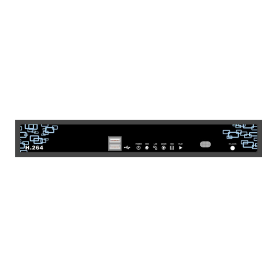
CHAPTER 2 PANEL LOCATION 2-1 FRONT PANEL CONTROLS ② ③ ⑤ ① ④ ⑥ ⑦ ⑧ Top(USB2.0) is used to plug the USB memory stick ○ USB Port Bottom(USB1.1) is used to plug the mouse ○ DVR Power is on. Power LED Display- ○... -
Page 9: 4Ch Rear Panel Connectors
2-2 4CH REAR PANEL CONNECTORS ① ③ ④ ⑧ ② ⑤ ⑥ ⑦ ① Socket for a DC 12V input. DC 12V ② MAIN monitor BNC port for the main monitor. ③ VIDEO IN BNC input ports for cameras, 16 in total. ④... -
Page 10: Chapter 3 Live, Playback And Ptz Operations
CHAPTER 3 LIVE, PLAYBACK AND PTZ OPERATIONS The IR remote control and mouse operate differently under each mode; this chapter describes the functions of them under three different modes: LIVE, PLAYBACK and PTZ. 3-1 LIVE Mode You can monitor all the channels, listen to audio signal and have some related operations under LIVE mode. - Page 11 Table 3-1.2 Graphical icons that will display after right-clicking your mouse under LIVE mode. Icon Description Resting the cursor on this icon will bring up the following three menu icons. Main menu. Search menu. Backup menu. Turn on/off recording. Playback. Resting the cursor on this icon will bring up the following five display icons.
- Page 12 Table 3-1.3 Description of on screen graphical icons in LIVE mode Icon Description Recording is on Schedule Recording is on Live Audio is on Live Audio is off Motion detected on the channel Sensor triggered on the channel Video loss detected on the channel USB device detected DVD burner is detected Connected to the LAN cable.
-
Page 13: Playback Mode
3-2 PLAYBACK Mode Switch to PLAYBACK mode by pressing “PLAY” under the LIVE mode, the graphical icon will show up on the upper center of the screen and the operation panel ( see below picture) will show up at right lower corner of the screen. You can drag the panel by mouse to place it on any location of your screen. - Page 14 Table 3-2.2 The mouse operation under the PLAYBACK mode. Icon Description 「 」 Fast rewind 「 」Fast forward Play/pause / 「▲ / SLOW」 ,slow playback 「▼ / ■」stop playback Playback channel by channel with snap shot display Full screen display Quad display Zoom-in display...
-
Page 15: Chapter 4 Main Menu Setup
CHAPTER 4 MAIN MENU SETUP To enter the main menu and set up DVR, log-in account and user password are required. The default password of the administrator is “123456”. Please check the “Account Setup” for related setup of other log-in users. Table 4-0.1 Some definition of virtual keyboard. -
Page 16: Record Setup
Table 4-0.2 The operation of remote control under the setting menu Item Description Switch to different options under one item Switch to different items MENU Save setup and back to LIVE mode Back to Upper level of menu without saving ENTER Enter the menu, or display virtual keyboard PS. -
Page 17: 4-1.1 Quality & Frame Rate Setup
4-1.1 Quality & Frame Rate Setup Note:4CH DVR will display 4 channels and 8CH DVR will display 8 channels. Item Description View Normal / Select recording mode View Event Check/uncheck the box enable/disable selected channel recording Select recording resolution: NTSC:360x240, 720x240, 720x480 Resolution PAL:352X288,704X288,704X576 Quality... -
Page 18: 4-2.1 Motion Setup
4-2.1 MOTION SETUP Item Description When motion detect,the number of seconds continuous alarm Alarm Duration(Seconds) Check the box to Enable/Disable popup screen function for all Motion Popup channels. When motion is detected in LIVE mode, the detected channel image will pop up in full screen display. You can setup independently for each channel. -
Page 19: Schedule Setup
Item Description Mask Mouse Selection Switch between “select” and “deselect” for cursor-dragging function All Area Detection Select entire screen as detection area. Mask All Area Deselect entire detection area. Continue Continue setup Exit & Save Save setup and leave Exit & Discard Cancel setup and leave 4-3 SCHEDULE SETUP Except from starting recording manually, you can also setup the recording time by weeks... -
Page 20: 4-3.1 Schedule Record Setup
4-3.1 Schedule Record Setup Click on the time on the left side. The setup menu will be displayed. You can have detail setup by dates, Time and event. 4-3.2 Holiday Setup Since holidays are different by different country and region, you can setup the holiday of your location accordingly. -
Page 21: Camera Setup
4-4 CAMERA SETUP Item Description You can setup independently for each channel. Mask Check the box to Enable/Disable mask function for LIVE mode Drag the bar or press ◀ ▶ to adjust Sharpness of your camera from Sharpness value 1 to 255. The default value is 1. Drag the bar or press ◀... -
Page 22: Account Setup
4-5 ACCOUNT SETUP The Account Setup menu is used to provide role-based permission independently setting for each user (maximum of 2 users) to access DVR over network. The default admin account and password is “admin” and “123456” The default password remains the same after firmware upgrade, however, it requires 8-digits for password length when you setup a new one Item Description... -
Page 23: 4-5.2 User Picture Setup
4-5.2 User Picture Setup User can select picture wished to be changed to from hard drive. 4-6 NETWORKING SETUP Item Description Connect type Setup mode for network connection: (DHCP、LAN、ADSL). HTTP Setup Enter to set up HTTP DDNS Setup Enter to set up DDNS Mail Setup Enter to set up mail... -
Page 24: 4-6.1 Networking Setup
4-6.1 NETWORKING SETUP There are three ways to connect to the network as followed. 4-6.1.1 DHCP When DHCP is selected, IP address will be assigned by DHCP server automatically. 4-6.1.2 LAN Select LAN for network connection, the following information is required. Item Description IP Address... -
Page 25: 4-6.1.3 Adsl
4-6.1.3 ADSL Select ADSL for network connection, the following information is required. Item Description User Name Enter user name provided by ISP Password Enter password provided by ISP 4-6.2 HTTP Setup Item Description Enable HTTP Check to enable HTTP server. Users can remotely access into the Server DVR over the network if the HTTP function is activated. -
Page 26: 4-6.3 Ddns Setup
4-6.3 DDNS Setup Item Description Enable DDNS Enable/disable DDNS function. Enter the registered SMTP Server: DDNS Server 、DYNDNS.ORG、NO-IP.ORG、3322.ORG ez-dns、I-DVR.NET* SMTP Server Enter the completed registered SMTP Server. (Including username + Server) If the user name is h.264 and you choose i-dvr as your server, you should enter: h.264.i-dvr.net User Name... -
Page 27: System Setup
Item Description Enable E-mail Notification Check the box to enable/disable E-mal Notification function. Enter to set up SMTP Server name. SMTP Server (Varies according to the user) User Name Enter to set up User Name. Password Enter to set up Password. Sender E-mail Enter to set up e-mail address of receivers. -
Page 28: 4-7.1 Display Setup
4-7.1 DISPLAY SETUP Item Description Auto-Seq Interval Set up duration time in seconds for the interval between channels under Auto-Seq mode. Show OSD Turn On / Off OSD display Show DVR Status Turn On / Off DVR illustration and record status display Show Date/Time Turn On / Off date and time display Show Channel Name... -
Page 29: 4-7.2.1 Change Date & Time
4-7.2.1 CHANGE DATE & TIME Setup date and time of DVR manually according to user’s local time. 4-7.2.2 TIME ZONE AND DAYLIGHT SAVING TIME SETUP Set up time zone and activate Daylight Saving Time function according to user’s DVR location. Item Description Select Time Zone... -
Page 30: 4-7.2.3 Internet Time Setup
4-7.2.3 INTERNET TIME SETUP Synchronize your DVR time with internet time server. Item Description Check to enable DVR automatic synchronization function. Effective by Automatic this option selected, DVR will automatically synchronize the time upon Synchronization rebooting or by every 24 hours after booting. Effectively, Date and Time show on DVR will immediately correspond Update Now with those in internet server. -
Page 31: Utility Setup
4-8 UTILITY SETUP Item Description Select to enter hard disk initialization menu. Please stop HDD Initialization recording before entering this menu. Enter the menu, system will show all the data (model ,volume ) of HDD that installed in DVR. Check the HDD you’d like to initialize then press “Start”. -
Page 32: Diagnostic
4-9 DIAGNOSTIC Item Description Version The current firmware version of DVR The connected IP address of DVR. If disconnected from network, the screen will display” NETWORK DISCONNECT”. MAC Address of DVR HDD Status HDD number Volume HDD Capacity Used Rate Percentage of space used on HDD. -
Page 33: Chapter 5 Backup & Search
CHAPTER 5 BACKUP & SEARCH 5-1 BACKUP SETUP User can backup any segment of recorded data in a specified time frame. To do so, either a CD R/W or storage device, like USB, must be connected to the DVR. Recorded data can also backup into NB/PC through our remote access software: 「DVRemoteDesktop.exe」... -
Page 34: Search Setup
5-2 SEARCH SETUP Item Description Event Search Event search menu Time Search Enter time search menu... -
Page 35: 5-2.1 Event Search
5-2.1 EVENT SEARCH The DVR automatically records events with type, time and channel information included. If there is recording data for an event, a yellow signal will be shown on the left side of time information. Rest your cursor under the line and press “enter”, or left click your mouse to playback the recording data. -
Page 36: 5-2.2 Time Search
5-2.2 TIME SEARCH TIME SEARCH can search for the specific time of recording data to playback. Press “Enter” or left click on the desired date to playback. Note that dates with recording data are marked with a □ red square “ “System will start playing back according to the date you selected. -
Page 37: Chapter 6 Rempte Software Installation And Setup
CHAPTER 6 Rempte Software Installation and Setup 6-1 AP Software Installation and instruction AP software:「DVR Remote Desktop」can allow you to remotely access and control the DVR from PC. p.s. Operation system currently supports Windows XP SP2 and above and Window s Vista, Windows 7 Step One:Enter the IP address of DVR in IE browser Step Two: Windows as below will show up. - Page 38 Step Four: Run or Save our AP software. Step Five: If you choose to run the software, Start window will be shown up. Please enter information of login DVR: IP, Port, Username and Password, or choose “Play Recorded File” to open backup files in your PC. Step Six: You’ve logged into the DVR...
-
Page 39: How To Do Remote Monitoring Through Ie
6-2 How to do remote monitoring through IE Step One:Enter the IP address of DVR in IE browser. The address appeared in this image is only for demonstration. Actual address is depending on the setup of on-site DVR. Step Two: Windows as below will show up. Please enter the user name and password. Default user name and password is admin/123456. -
Page 40: Ap Software Operation
Step Four: DVR images appear. 6-3 AP Software Operation Open the file “DVRemoteDesktop.exe”; enter the information of DVR “IP address”, “Port” “Username” and “Password” and click “OK”. You should be able to login DVR successfully and start to use the software. The default username and password is 「admin/ 123456」 “DVRemoteDesktop.exe”... -
Page 41: Chapter 7 Specificaitons
CHAPTER 7 SPECIFICAITONS 1. VIDEO Input Level 1.0 Vp-p±10% Composite, 75 Balanced NTSC 120fps Display Speed 100fps NTSC 720(H) X 480(V) Display Resolution 704(H) X 576(V) Monitor Output 2Vp-p Composite, 75 Balanced 2. RECORDING Compression Method H.264 Recording Speed Refer to table 7-1 NTSC 720 X 480, 720 X 240, 360 X 240 Recording Resolution... - Page 42 8. BACKUP USB Stick Video Data, Audio BACKUP Network Video Data, Audio 9. SEARCHING & PLAYBACK Searching Type Event/ Time Playback speed 120 FPS 10. MULTI-REMOTE SURVEILLANCE Monitoring Environment Web/AP/CMS Max. client Supporting multi-client (3 clients accessible) 11. OTHERS Embedded Linux Live、Record、Playback、Network、Backup Multi Task Pentaplex...
-
Page 43: Chapter 8 Mobile Application Installation And Usage
CHAPTER 8 MOBILE APPLICATION INSTALLATION AND USAGE You can remotely monitor all channels of DVR through your mobile device. The required mobile application is from DVR manufacturer and it supports mobile OS for both Windows mobile 5.0 above and Symbian. Please confirm network function of DVR has been activated before mobile connection: Main menu ... -
Page 44: 8-1.2 Mobile Application Operation
8-1.2 Mobile Application Operation After the installation, enter the Program Files menu in your mobile device to run a file called “DVRH264”. Select “Menu” at the right lower corner of your mobile screen, 4 commands, Login Add Modify and Delete, will show up. -
Page 45: 8-1.2.3 Modify The Login Information Of Dvr
8-1.2.3 Modify the Login Information of DVR You can use the “Modify” command to change the login information of DVR. The dialogue is identical to that of the “Add” command. 8-1.2.4 Delete the Login Information of DVR “Delete” command can be used to remove the DVR information if it is no longer useful. Select the DVR on the name list then choose “Delete”... -
Page 46: 8-1.3.1 Scroll The Image
8-1.3.1 Scroll the Image You can use the keypad on your mobile device to scroll the image if it’s oversized. Action Scroll Up Scroll Left Scroll Right Scroll Down 8-1.3.2 Image Quality Setup Select “Quality” under the “Menu” There will be 5 levels for your to choose: Low、 Normal、Middle、High and Highest. -
Page 47: 8-1.3.4 Size Of Image
8-1.3.4 Size of Image The screen size of different mobile device can be different. You can select “Size” under the “Menu” to choose from “Original” or “Fit Screen” to resize the display image. Item Description Original The image will be shown in original size. -
Page 48: Mobile Application Installation And Operation For Windows Mobile System
8-2 Mobile Application Installation and Operation for Windows Mobile System There are two kinds of applications for Window Mobile OS: JPEG compression and H.264 compression. The one for H.264 compression can transfer both audio and video signal to your mobile device. System Requirement: Mobile device OS:Windows mobile system 5.0 above. -
Page 49: 8-2.2 Mobile Application Operation
8-2.2 Mobile Application Operation After the installation, enter the Program Files menu in your mobile device to run files named “Jrviewer” and “H264Pocket”. This application allows you to remotely logon and monitor DVR. Press “OK” to bring up the operation menu, see below chart to further information. Item Function Description... -
Page 50: 8-2.3 Operation Under The Live Monitoring
8-2.3 Operation under the LIVE monitoring. After successful logon the DVR, press “View” to bring up operation menu. You can choose the channel, resize the image, choose the quality, and turn on/off the status bar, alarm, full screen display….etc Item Function Description Choose from CH1~16 to display. -
Page 51: Chapter 9 Cms Installation And Usage Guide
CHAPTER 9 CMS INSTALLATION AND USAGE GUIDE 9-1 CMS Installation System Requirement: Intel Pentium 4 processor or equivalent. * Microsoft Windows Vista、Windows XP、Windows 2003 Server. * Besides OS and other required APs, there will be 512MB remaining memory needed or above. *... - Page 52 5.”Confirm Installation” window shows. Select ‘Next’ then the installation starts. 6. Select ‘Close’ to finish installation when the “Installation Complete” window shows.
-
Page 53: Instruction For Log-In Failure To Cms After Upgrade
Instruction for Log-in Failure to CMS After Upgrade Log in to CMS with the default account and password after CMS upgrade. If an error message occurs as shown in the image, please follow the instruction to solve the error. Step 1: Please enter file manager to enter folder, “Windows” and then folder “Systme32” (ex:C:\Windows\System32) Step 2: Locate file, “iCMS.dat”... -
Page 54: Cms Login And Environment
9-2 CMS LOGIN AND ENVIRONMENT To enter CMS, the administrator’s user name and password are required. The defaults are ‘admin’ and ‘123456’. After successful login, the following image shows on your screen: ③ ① ② ④ ⑤ ① DVRs, Groups & Information about DVRs, groups and events. -
Page 55: Dvrs, Groups & Events
9-3 DVRs, Groups & Events Icon Description View list of logged in DVR/ Group. View Logs: list all the event information of DVR / 9-3.1 View DVR Group List Single left click on ‘DVR’ or ‘Group’ will expand/collapse the entire DVRs and groups list. -
Page 56: 9-3.2 View Event Logs
9-3.2 View Event Logs Under this page, all the events of a DVR can be expanded/collapsed in the order of Re mote in/Remote out, Video Loss, Motion, Sensor, Others (Power Reset, Key Lock, Key Unlock, HD Full). 9-4 Local PC Information and Control Located at the left lower corner of the screen, please see the chart below: Icon Function... -
Page 57: Main Display
9-5 Main Display The main display area is where the live image of DVR is shown. You can drag to change the location of screen for each channel and turn on/off audio signal with mouse-click. 9-5.1 Audio Control In live mode, you can turn on/off the audio signal of Ch1~Ch4: 「... -
Page 58: 9-5.2 Emap Display
9-5.2 eMAP Display In Live mode, pressing will bring the e-MAP drag-down menu. If the channel has been set up to use e-MAP, the menu will show all the e-MAP titles that have been entitled to this channel; otherwise, “No eMaps” will be shown. Please check “9-6.4 eMAP administration”... -
Page 59: 9-5.3 Ptz Control
9-5.3 PTZ Control In the main display, right click on the channel will bring up PTZ control panel as below. Icon Description 8 direction key Rotate the PTZ ZOOM+:Zoom in ZOOM : Zoom out Setup the PTZ spot as pre-set N. FOCUS+ : Focus in FOCUS-:Focus out Move to pre-set N. -
Page 60: Operation Bar
9-6 Operation Bar 10 Operations to be listed as below: Table 9-6.1 description of 10 operations: Icon Description User Administration. Please see “9-6.1 User administration” DVR Administration. Please see “9-6.2 DVR Administration” Group Administration. Please see “9-6.3 Group Administration” eMap Administration. Please see “9-6.4 eMap Administration”. Remote Playback. -
Page 61: 9-6.1 User Administration
9-6.1 User administration Before the CMS can be used on a PC, user accounts should be added with proper authority. Each user should also be assigned a password and optionally a description. If a user does not have certain authority assigned, he/she will not be able to operate the corresponding function on the Operation Bar. -
Page 62: 9-6.3 Group Administration
9-6.3 Group Administration A ‘Group’ means a set of video channels from one or many DVRs, which means, user can organize channels from different DVRs to be set in a group. This function allows you to monitor and manager channels from multiple DVRs easily and flexible. Steps: 1. -
Page 63: 9-6.4 Emap Administration
9-6.4 eMap Administration If geographical locations are relevant, or if it is desired to use a picture as the background, eMap can be used for the purpose. With eMap, the background picture can be picked by the user and channels from multiple DVRs can be placed and dragged around on the picture. Steps to follow: 1. -
Page 64: 9-6.5 Remote Play
9-6.5 Remote Play Video images recorded on a DVR can be displayed on a remote CMS. With Remote Play function, select a DVR and a display mode on top of the screen. After the recorded segments are listed below, double click on one to show its image on the right. Icon Description Start playing. -
Page 65: 9-6.6 Hdd Playback
9-6.6 HDD Playback You can directly play the recording data in the HDD that’s uninstalled from DVR by CMS. See the picture below, the left part of screen is recording data in list that’s separated by hour and the right part is main display. You can change the display modes and play files fast forward or rewind. -
Page 66: 9-6.8 Event Playback
9-6.8 Event Playback Event recordings on the DVR can be played back in CMS. Steps to follow: 1. Select a DVR and a display mode. 2. Select a date. 3. Double click an event and play back the images on the right. Use buttons at the bottom to control the playback. -
Page 67: 9-6.10 Recording Data
9-6.10 Recording Data It can play all the recording files you’ve recorded in line in “Recording Data”. You can play or delete them here. Steps to follow: 1. Choose the recording time at upper left corner, it will be played on the main display. 2. -
Page 68: Appendix I I-Dvr.net Registration
APPENDIX I I-DVR.NET REGISTRATION DDNS Registration on I-DVR.NET In the package of each DVR, you will find a sticker shows account information including username and password that allows users to login I-DVR.NET for registration. To register DDNS on I-DVR.NET, please follow the steps as shown. Step 1. - Page 69 Step 4. Enter DVR →Main Menu → Network Setup → DDNS. Activate DDNS functions and input related information. DDNS work properly when this option selected. This part of the information required and the same within the i-dvr.net Step 5.Back to the i-dvr.net, on this page by pressing "F5: Refresh", IP will be automatically updated into the DVR of the real IP location.
-
Page 70: Appendix Ii Remote Monitoring Ie Activex Control Installation Instruction
APPENDIX II Remote Monitoring IE ActiveX Control Installation Instruction When using IE for remote monitoring for the first time, IE ActiveX Control is needed to be downloaded. 1. When remote monitoring on IE for the first time, an alert message occurs “Install ActiveX control”... - Page 71 4. After installation, IE remote monitoring image appears. 5. If message, “Your security Settings do not allow web sites to use ActiveX controls installed on your computer.” pops on when logging in, please follow the next instruction. 6. First select “Tools” on the tool bar and then select “Internet Options”...
- Page 72 7. Select Security →Trusted Sites → Sites 8. Enter DVR address (This address is only for demonstration. Please use the address depends on the setup of on-site DVR.) into the blanks shown in picture, and then press “add.”...
- Page 73 9. Newly added website will appear at the trusted web sites list. Press close. 10. Go back to IE window, press refresh button or F5.
Need help?
Do you have a question about the 411L and is the answer not in the manual?
Questions and answers