Table of Contents
Advertisement
Advertisement
Table of Contents

Related Manuals for Manitowoc RNS012


Summary of Contents for Manitowoc RNS012
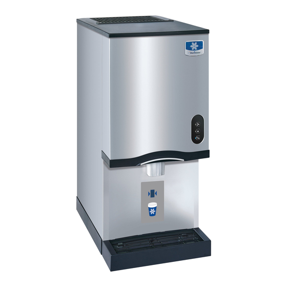
- Page 1 Manitowoc RNS012 & RNS020 Nugget Ice Machines Technician’s Handbook This manual is updated as new information and models are released. Visit our website for the latest manual. www.manitowocice.com America’s #1 Selling Ice Machine Part Number STH044 10/13...
-
Page 3: Safety Notices
Safety Notices As you work on Manitowoc equipment, be sure to pay close attention to the safety notices in this handbook. Disregarding the notices may lead to serious injury and/or damage to the equipment. Throughout this handbook, you will see the following... - Page 4 ! Caution Proper installation, care and maintenance are essential for maximum performance and trouble- free operation of your Manitowoc equipment. Visit our website www.manitowocfsg.com for manual updates, translations, or contact information for service agents in your area. If you encounter problems not covered by this manual, do not proceed, contact Manitowoc Foodservice Group.
- Page 5 Warning Do not use electrical appliances or accessories other than those supplied by Manitowoc for your ice machine model. Warning Two or more people or a lifting device are required to lift this appliance.
- Page 6 Warning Do not operate equipment that has been misused, abused, neglected, damaged, altered/modified from that original manufactured specifications. This appliance is not intended for use by persons (including children) with reduced physical, sensory or mental capabilities, or lack of experience and knowledge, unless they have been given supervision concerning use of the appliance by a person responsible for their safety.
- Page 7 Warning It is the responsibility of the equipment owner to perform a Personal Protective Equipment Hazard Assessment to ensure adequate protection during maintenance procedures. Warning When using electric appliances, basic precautions must always be followed, including the following: a. Read all the instructions before using the appliance.
-
Page 9: Table Of Contents
Model Numbers ..... 5 Model/Serial Number Location ..5 Manitowoc Cleaner and Sanitizer ..5 Ice Machine Warranty Information . . . 6 Commercial Warranty . - Page 10 Maintenance Manitowoc’s Cleaning Technology ..26 Exterior Cleaning ....27 Preventative Maintenance Procedure . . 28 Heavily Scaled Cleaning Procedure ..31 Cleaning And Sanitizing Procedure .
- Page 11 Component Check Procedures Main Fuse ..... . 73 ICE/OFF/CLEAN Toggle Switch ..74 Float Switch ..... 75 Ice Damper and Hall Effect Switches .
- Page 12 RNS012 - RNS020 Control Board . . . 109 Refrigeration Tubing Schematic ..111 RNS012 - RNS020 ....111 Part Number STH044 10/13...
-
Page 13: General Information
Model/Serial Number Location These numbers are required when requesting information from your local Manitowoc Distributor, service representative, or Manitowoc Ice, Inc. The model and serial number are listed on the OWNER WARRANTY REGISTRATION CARD. They are also listed on the MODEL/SERIAL NUMBER DECAL affixed to the ice machine. -
Page 14: Ice Machine Warranty Information
REGISTRATION CARD as soon as possible to validate the installation date. If the OWNER WARRANTY REGISTRATION CARD is not returned, Manitowoc will use the date of sale to the Manitowoc Distributor as the first day of warranty coverage for your new ice machine. - Page 15 Time and hourly rate schedules, as published from time to time by the COMPANY, apply to all service procedures. Additional expenses including without limitation, travel time, overtime premium, material cost, accessing or removal of the ice machine, or shipping are the responsibility of the owner, along with all maintenance, adjustments, cleaning, and ice purchases.
- Page 16 Complete the following and retain for your record: Distributor/Dealer Model Number Serial Number Installation Date MANITOWOC ICE 2110 So. 26 St., P.O. Box 1720, Manitowoc, WI 54220 Telephone: 920-682-0161 • Fax: 920-683-7585 Web Site - www.manitowocice.com Part Number STH044 10/13...
-
Page 17: Residential Warranty
Subject to the exclusions and limitations below, Manitowoc Ice (“Manitowoc”) warrants to the original consumer that any new ice machine manufactured by Manitowoc (the “Product”) shall be free of defects in material or workmanship for the warranty period outlined below under normal use and maintenance,... - Page 18 WHAT ARE MANITOWOC ICE’S OBLIGATIONS UNDER THIS LIMITED WARRANTY? If a defect arises and Manitowoc receives a valid warranty claim prior to the expiration of the warranty period, Manitowoc shall, at its option: (1) repair the Product at Manitowoc’s cost, including standard...
- Page 19 (5) defects or damage to any Product that has not been installed and/or maintained in accordance with the instruction manual or technical instructions provided by Manitowoc. To the extent that warranty exclusions are not permitted under some state laws, these exclusions may not apply to you.
- Page 20 REGISTRATION CARD To secure prompt and continuing warranty service, this warranty registration card must be completed and sent to Manitowoc within thirty (30) days from the sale date. Complete the registration card and send it to Manitowoc. Part Number STH044 10/13...
-
Page 21: Installation
Installation Warning PERSONAL INJURY POTENTIAL Remove all ice machine panels before lifting and installing. Location of Ice Machine The location selected for the ice machine must meet the following criteria. If any of these criteria are not met, select another location. •... -
Page 22: Ice Machine Clearance Requirements
Self-Contained Air-Cooled 24" (61.0 cm) Sides 8" (20.3 cm) Back 5" (12.7 cm) RNS012 - RNS020 airflow is in the left side and out the top. Ice Machine Heat of Rejection Heat of Rejection* Series Ice Machine Air Conditioning RNS012 - RNS020... -
Page 23: Electrical Service
The wire size (or gauge) is also dependent upon location, materials used, length of run, etc., so it must be determined by a qualified electrician. Self Contained Air-Cooled Max. Fuse/ Voltage Total Circuit Machine Phase Cycle Amps Breaker 115/1/60 10.3 RNS012 RNS020 230/1/50 Part Number STH044 10/13... -
Page 24: Ice Machine Head Section Water Supply And Drains
Important If you are installing a Manitowoc water filter system, refer to the Installation Instructions supplied with the filter system for ice making water inlet connections. POTABLE WATER INLET LINES Follow these guidelines to install water inlet lines: •... -
Page 25: Drain Connections
DRAIN CONNECTIONS Follow these guidelines when installing drain lines to prevent drain water from flowing back into the ice machine and storage bin: • Drain lines must have a 1.5 in. (3.8 cm) drop per 5 ft. of run (2.5 cm per meter), and must not create traps. - Page 26 This Page Intentionally Left Blank Part Number STH044 10/13...
-
Page 27: Operation
Operation Ice Making Sequence of Operation RNS012 - RNS020 NUGGET MACHINES Ice Making Sequence of Operation PRIOR TO STARTUP When the toggle switch is placed in the ICE position the following must occur in the listed order before ice making will start. - Page 28 AUTOMATIC SHUTOFF When the ice damper is held open by ice, the gear motor, compressor and condenser fan de-energize. The five minute delay period starts to time out. The ice machine will remain off until the 15 minute delay period expires and the ice damper closes. RESTART AFTER AUTOMATIC SHUTOFF The 15 minute delay period must be expired.
-
Page 29: Touch Pad Sequence Of Operation
Control Board Features FLUSH CYCLE After the ice machine has completed 50 hours of run time a flush sequence will start. This cycle will drain and refill the evaporator to remove minerals that have settled to the bottom of the evaporator. The flush sequence lasts approximately 21 minutes, after which the ice machine will reset the 50 hour counter and automatically start ice making again. -
Page 30: Sequence Of Operation Chart
SEQUENCE OF OPERATION CHART Nugget Machines Contactor Dump Gear Sequence Ice Damper Duration Coil Valve Motor Initial Start-Up The 15 minute delay must expire Closed Immediate first Moves to Verify Until Ice Holds Damper Freeze Cycle Ice Production Open Automatic Shut-Off Open Until Damper Closes Restart... -
Page 31: Water Level Check
WATER LEVEL CHECK The float valve maintains the correct water level. The water level is factory set and normally will not require adjustment. The water level is correct if the Water Level indicator light is energized and no water is entering the overflow tube. - Page 32 This Page Intentionally Left Blank Part Number STH044 10/13...
-
Page 33: Maintenance
Maintenance Maintenance procedures or failures due to a lack of maintenance are not covered by the warranty. Manitowoc Ice Machine Cleaner and Sanitizer are the only products approved for use in Manitowoc ice machines. ! Caution Use the correct Manitowoc approved metal safe Ice Machine Cleaner (part number 000000084) and Sanitizer (part number 94-0565-3). -
Page 34: Manitowoc's Cleaning Technology
Manitowoc’s Cleaning Technology Manitowoc RNS012 - RNS020 Ice Machines allow the initiation and completion of a cleaning cycle at the flip of a switch. This cycle will permit cleaning of all surfaces that come in contact with the water distribution system. Periodic maintenance must be... -
Page 35: Exterior Cleaning
Preventative Maintenance Cleaning Procedure Perform this procedure as often as required for your water conditions: • Allows cleaning the ice machine without removing all of the ice from the bin/dispenser. • Removes mineral deposits from areas that are in direct contact with water during the Freeze cycle (reservoir, evaporator, auger, drain lines). -
Page 36: Preventative Maintenance Procedure
Step 2 Remove the cover from the top of the ice chute. Wait about one minute then add the proper amount of Manitowoc Ice Machine Cleaner and re- install cover. ! Caution Use only Manitowoc approved Ice Machine Cleaner part number 000000084. - Page 37 ADD SOLUTION HERE WATER ICE / WATER Step 3 The ice machine will automatically time out a series of flush and rinse cycles, and then stops. This entire cycle lasts approximately 30 minutes. NOTE: Periodic cleaning must be performed on adjacent surface areas not contacted by the water distribution system.
- Page 38 3. To abort the clean cycle move the toggle switch from CLEAN to OFF to CLEAN and back to OFF within a 15 second time period. Manitowoc recommends disassembling, cleaning and sanitizing the ice machine and dispenser every six months.
-
Page 39: Heavily Scaled Cleaning Procedure
OFF position. Step 6 Refer to chart and add the correct amount of cleaner for your model ice machine. Amount of Cleaner Model Part Number 000000084 RNS012 RNS020 16 ounces (473 ml) Part Number STH044 10/13... - Page 40 ADD SOLUTION HERE WATER ICE / WATER Step 1 Turn on the water supply to the ice machine. Important Leave cleaner/water solution evaporator for a minimum of 4 hours. Step 2 Move the toggle switch to the ICE position. The compressor will energize and produce ice with the cleaning solution.
-
Page 41: Cleaning And Sanitizing Procedure
OFF position. ! Caution Use only Manitowoc approved Ice Machine Cleaner part number 000000084. It is a violation of Federal law to use these solutions in a manner inconsistent with their labeling. Read and understand all labels printed on bottles before use. - Page 42 Amount of Model Water Part Number 000000084 RNS012 RNS020 2 oz (60 ml) 32 oz (1 liter) Step 7 Remove the top cover from the ice chute and pour the cleaner/water solution into the evaporator. Add the entire amount of premixed solution (excess solution will exit through the overflow tube in the water reservoir).
- Page 43 Step 17 Remove the top cover from the ice chute and pour the sanitizer/water solution into the evaporator. Add the entire amount of premixed solution (excess solution will exit through the overflow tube in the water reservoir). Step 18 Replace the ice chute cover and allow the ice machine to stand for 30 minutes.
-
Page 44: Component Disassembly For Cleaning And Sanitizing
Component Disassembly For Cleaning And Sanitizing Warning Disconnect electric power to the ice machine at the electric switch box before proceeding. Warning Wear rubber gloves and safety goggles (and/or face shield) when handling Ice Machine Cleaner or Sanitizer. ! Caution Do not mix Cleaner and Sanitizer solutions together. - Page 45 Removal of Parts for Cleaning or Sanitizing 1. Turn off water supply to ice machine. 2. Place toggle switch in the clean position for 30 seconds to drain water from reservoir, then move toggle switch to Off position. 3. Run dispenser to transfer all ice from the bin to a container.
- Page 46 6. Remove front cover. A. Lift up on front cover. B. Pull forward to disengage keyhole slots. 7. Remove side panels. Part Number STH044 10/13...
- Page 47 8. Remove ice chute cover A. Turn the two thumbscrews 1/4 turn. B. Lift to remove cover. LOOSEN SCREWS Part Number STH044 10/13...
- Page 48 9. Lift out ice damper. Part Number STH044 10/13...
- Page 49 10. Lift out ice strainer ramp. Part Number STH044 10/13...
- Page 50 11. Turn ice wiper counterclockwise to remove. Part Number STH044 10/13...
- Page 51 12. Loosen ice chute hose clamp. 13. Disconnect ice chute drain. 14. Lift up on ice chute to remove. The ice chute must be removed before the bin cover can be removed. Part Number STH044 10/13...
- Page 52 15. The ice chute can be cleaned in place. If complete removal is desired use a phillips screwdriver to remove the Hall Effect Switch assembly from the ice chute. REMOVE SCREW Part Number STH044 10/13...
- Page 53 16. Remove three thumbscrews, then remove bin cover. REMOVE THUMBSCREWS Part Number STH044 10/13...
- Page 54 17. Remove agitator bar. • RNS012 - Remove the thumbscrew and lift off. • RNS020 - Unscrew the upright agitator bar. NOTE: Bar must be reassembled by inserting front edge into the paddle wheel, then lowering the back edge (rounded 90 angle) to prevent water leakage into the compressor compartment.
- Page 55 18. Remove ice deflector. A. Remove the two thumbscrews. B. Lift the ice deflector out. REMOVE THUMBSCREW Part Number STH044 10/13...
- Page 56 19. Remove ice dispensing wheel by lifting straight out. Part Number STH044 10/13...
- Page 57 20. Water Reservoir Cover Removal A. Push up on cover to snap off. Part Number STH044 10/13...
-
Page 58: Water Dump Valve
WATER DUMP VALVE The water dump valve normally does not require removal for cleaning. To determine if removal is necessary: 1. Set the toggle switch to OFF. 2. Watch the water float valve. If the dump valve is leaking the float will continue to add water in the Off cycle. - Page 59 4. Remove the tubing from the dump valve by twisting the clamps off. 5. Remove the valve body from mounting bracket by twisting counterclockwise. COIL SPRING NYLON WASHER PLUNGER DIAPHRAM MOUNTING BRACKET VALVE BODY Dump Valve Disassembly Part Number STH044 10/13...
-
Page 60: Cleaning The Condenser
CLEANING THE CONDENSER Warning Disconnect electric power to the ice machine at the electric service switch before cleaning condenser. The condenser fins are sharp. Use care when cleaning them. A dirty condenser restricts airflow, resulting in excessively high operating temperatures. This reduces ice production and shortens component life. -
Page 61: Removal From Service/Winterization
Removal from Service/Winterization GENERAL Special precautions must be taken if the ice machine is to be removed from service for an extended period of time or exposed to ambient temperatures of 32°F (0°C) or below. ! Caution If water is allowed to remain in the ice machine in freezing temperatures, severe damage to some components could result. - Page 62 This Page Intentionally Left Blank Part Number STH044 10/13...
-
Page 63: Troubleshooting
Troubleshooting SafeGuard Feature The ice machine will stop when conditions arise that would cause major component failure. Standby Mode The first time a failure occurs, the ice machine de- energizes and initiates a Standby Mode. The ice machine will remain off for 60 minutes, then automatically restart to see if the problem reoccurs. - Page 64 Reset Procedure 1. Move the ICE/OFF/CLEAN toggle switch to OFF. A. If a safeguard feature has stopped the ice machine, it will restart after a short delay. Proceed to Step 2. B. If the ice machine does not restart, see “Ice Machine Does Not Operate.”...
-
Page 65: Safeguards
SafeGuards • No Water • No Ice Production NO WATER The water sensing switch opens for more than 30 seconds. Operation When the float switch is open at initial start-up the ice machine will wait for the switch to close before starting. -
Page 66: No Ice Production
NO ICE PRODUCTION The ice damper did not open and close at least once every 90 seconds in the freeze cycle. OPERATION During the first 8 minutes of operation: The control board must see the ice damper open/close at least once. This allows time for ice production to start at all ambient temperatures After the initial 8 minute period: The control board must see the ice damper open/close... - Page 67 Reset Procedure Move the ICE/OFF/CLEAN toggle switch from OFF to ICE or disconnect and reapply power to the ice machine. Part Number STH044 10/13...
-
Page 68: Ice Machine Will Not Run Diagnostics
Ice Machine Will Not Run Diagnostics Warning High (line) voltage is applied to the control board (terminals #39 and #90) at all times. Removing control board fuse or moving the toggle switch to OFF will not remove the power supplied to the control board. - Page 69 Ice Machine Will Not Run IMPORTANT Power Supplied to Plug In Ice Machine, A Five Minute Delay Initiates After The Problem Is Ice Machine? Reset Breaker Corrected. This Delay Must Expire Before The Ice Machine Will Start. Reset Control Board, Disconnect And Reconnect Line Voltage...
- Page 70 IMPORTANT A Five Minute Delay Initiates After The Problem Is Corrected. This Delay Must Expire Before The Ice Power At Machine Will Start. Refer To High Pressure Cutout Terminals Specifications. #90 & #39? Disconnect HES #2 Nugget Control Board Replace Control From Control Board.
- Page 71 IMPORTANT Reservoir Full Of A Five Minute Delay Initiates After The Problem Is Restore Water Supply Water? Corrected. This Delay Must Expire Before The Ice Machine Will Start. Float Switch Light Refer To Float Switch Diagnostics Damper Door Install/Close Damper Door Closed?
- Page 72 IMPORTANT A Five Minute Delay Initiates After The Problem Is Refer To Hall HES #1 Light Corrected. This Delay Must Expire Before The Ice Effect Switch Energized? Diagnostics Machine Will Start. Hes # 2 Light Energized? Toggle Switch Functions? (If The Toggle Switch Energizes And Refer to Toggle De-Energizes The BLue Light, The Switch Diagnostics...
- Page 73 IMPORTANT 5 Minute Delay Wait For Delay To Expire, A Five Minute Delay Initiates After The Problem Is Expired? Then Refer To SafeGuards Corrected. This Delay Must Expire Before The Ice Machine Will Start. Refer to Gearmotor Control Board Fuse Compresor Energizes? Diagnostics Refer to...
-
Page 74: Refrigeration Diagnostics
Refrigeration Diagnostics BEFORE BEGINNING SERVICE Ice machines may experience operational problems only during certain times of the day or night. A machine may function properly while it is being serviced, but malfunctions later. Information provided by the user can help the technician start in the right direction, and may be a determining factor in the final diagnosis. -
Page 75: Water System Checklist
WATER SYSTEM CHECKLIST A water-related problem could cause component misdiagnosis. Water system problems must be identified and eliminated prior to replacing other components. Possible Problem List Corrective Action List Water area (evaporator) is Clean as needed. dirty. Install a water regulator Water inlet pressure not valve or increase the water between 20 and 80 psig. -
Page 76: Ice Production/Quality Check
ICE PRODUCTION/QUALITY CHECK QUALITY CHECK Ice quality will vary with ambient and water temperatures, and is measured by the amount of excess water in the ice. An easy test is to squeeze a handful of ice. High quality ice releases only a small amount of water. -
Page 77: Analyzing Discharge Pressure
High inlet air temperature air flow Condenser discharge air recirculation Dirty condenser fins Defective fan motor Improper Overcharged refrigerant Non-condensible in system charge Wrong type of refrigerant Other Non-Manitowoc components in system High side refrigerant line/component restricted (before mid-condenser) Part Number STH044 10/13... - Page 78 Checklist.” Improper Undercharged refrigerant Wrong type of refrigerant charge Low ambient temperature Non-Manitowoc components in system High side refrigerant lines/component restricted (before mid-condenser) Suction pressure is too low and affecting Other discharge pressure. (Refer to “Suction Pressure Low Checklist.”) No water or insufficient pressure...
-
Page 79: Analyzing Suction Pressure
Refer to pressure “Discharge Pressure High Checklist.” Improper Overcharged refrigerant Wrong type of refrigerant charge Non condensible in system Dump valve leaking Non-Manitowoc components in system Other Expansion valve incorrectly adjusted Defective compressor Part Number STH044 10/13... -
Page 80: Suction Pressure Low Checklist
“Discharge Pressure Low Checklist.” Improper Undercharged refrigerant Wrong type of refrigerant charge Other Non-Manitowoc components in system Restricted/plugged liquid line drier Restricted/plugged tubing in suction side of refrigeration system Expansion valve starving No water or insufficient pressure Moisture in refrigeration system... -
Page 81: Component Check Procedures
Component Check Procedures MAIN FUSE FUNCTION The control board fuse stops ice machine operation if electrical components fail, causing high amp draw. SPECIFICATIONS The main fuse is 250 Volt, 10 amp, time delay. Warning High (line) voltage is applied to the control board at all times. -
Page 82: Ice/Off/Clean Toggle Switch
ICE/OFF/CLEAN TOGGLE SWITCH FUNCTION The switch is used to place the ice machine in ICE, OFF or CLEAN mode of operation. SPECIFICATIONS Single-pole, double-throw switch. The switch is connected into a varying low D.C. voltage circuit. CHECK PROCEDURE NOTE: Because of a wide variation in D.C. voltage, it is not recommended that a voltmeter be used to check toggle switch operation. -
Page 83: Float Switch
FLOAT SWITCH FUNCTION The float switch prevents the ice machine from running when the water level is below the control setpoint. The float switch must be closed (float in up position) before the ice machine will start, and must remained closed throughout the freeze cycle. -
Page 84: Ice Damper And Hall Effect Switches
ICE DAMPER AND HALL EFFECT SWITCHES Damper Door FUNCTION Opens and closes as ice passes from the ice chute to the bin. A metal lever attached to the damper interrupts the magnetic field sensed by the hall effect switches as the damper opens and closes. Hall Effect Switch #1 - Operational Sensing This switch will open and re-close in conjunction with... - Page 85 Hall Effect Switch Diagnostics All diagnostics must be performed with the ice damper installed and in the closed position. The control board lights will not indicate as described below with the ice damper in the open position. The ice damper must swing freely, if the damper is binding adjust/loosen screws that hold the Hall Effect Switch Housing in place.
- Page 86 SWITCH FAILS CLOSED HES#1 1. Reset line voltage to the ice machine 2. Wait 15 minutes for delay to expire. 3. HES#1 light de-energized. 4. The ice machine starts, runs for 20 seconds, then de-energizes. 5. HES#1 light is de-energized. HES#2 1.
-
Page 87: Selector Switch
SELECTOR SWITCH FUNCTION Selects product dispensed. Ice, Water or Ice and Water. CHECK DISPENSE LEVER ACTIVATED Step 1 Verify line voltage is present at control board wires #20 & #22. Note - If a blue indicator light is energized on the touch pad the control board has line voltage. -
Page 88: Touchless Sensor Activated
TOUCHLESS SENSOR ACTIVATED Step 1 Verify line voltage is present at control board wires #20 & #22. Note - If a blue indicator light is energized on the touch pad the control board has line voltage. Step 2 Depress each selection on the touch pad. •... - Page 89 Will Not Stop Dispensing • Disconnect sensor plug from sensor control board. • If the dispensing stops, replace the sensor • If the dispensing continues disconnect wires #59 & #60 from the control board • Check resistance across control board contacts •...
-
Page 90: Dispense Switch
DISPENSE SWITCH FUNCTION Supplies power to the product selector switch when activation lever is depressed. CHECK 1. Inspect the selector switch for correct wiring. 2. Isolate the switch by disconnecting all wires from the switch. 3. Check across the switch terminals with an ohm meter. -
Page 91: Touchless Sensor
TOUCHLESS SENSOR FUNCTION Supplies power to the product selector switch when container activates sensor. CHECK Container must be within an inch of sensor to activate. Will Not Dispense 1. Verify power is supplied to the ice machine. When the toggle switch is in ICE position the blue LED light will be on. -
Page 92: High Pressure Cutout Control
HIGH PRESSURE CUTOUT CONTROL FUNCTION Stops the ice machine if subjected to excessive high- side pressure. The HPCO control is normally closed, and opens on a rise in discharge pressure. Specifications Cut-Out Cut-In 450 psig ±10 (3103 kPa ±69) Automatic Reset 31 bar ±.69 (Must be below 300 psig (2068 kPa 20.68 bar) to reset.) -
Page 93: Fan Cycle Control
FAN CYCLE CONTROL FUNCTION Energizes and de-energizes the condenser fan motor. The fan cycle control closes on an increase, and opens on a decrease in discharge pressure. Specifications Cut-In (Close) Cut-Out (Open) 250 psig ±5 200 psig ±5 CHECK PROCEDURE 1. -
Page 94: Low Pressure Cutout (Lpco) Control
LOW PRESSURE CUTOUT (LPCO) CONTROL FUNCTION Stops the ice machine if the low side pressure is too low. The LPCO control is closed at pressures above setpoint and opens at pressures below setpoint. Specifications Cut-Out Cut-In Current Production & 17 psig ±5 35 psig ±7 Replacement Part CHECK PROCEDURE... -
Page 95: Compressor Electrical Diagnostics
COMPRESSOR ELECTRICAL DIAGNOSTICS The compressor does not start or will trip repeatedly on overload. Check Resistance (Ohm) Values NOTE: Compressor windings can have very low ohm values. Use a properly calibrated meter. Perform the resistance test after the compressor cools. The compressor dome should be cool enough to touch (below 120°F/49°C) to assure that the overload is closed and the resistance readings will be accurate. - Page 96 Compressor Drawing Locked Rotor To determine if the compressor is seized, check the amp draw while the compressor is trying to start. The two likely causes of this are a defective starting component and a mechanically seized compressor. To determine which you have: 1.
-
Page 97: Diagnosing Start Components
DIAGNOSING START COMPONENTS If the compressor attempts to start, or hums and trips the overload protector, check the start components before replacing the compressor. Capacitor Visual evidence of capacitor failure can include a bulged terminal end or a ruptured membrane. Do not assume a capacitor is good if no visual evidence is present. - Page 98 Relay Operation Check Warning Disconnect electrical power to the ice machine before proceeding. 1. Disconnect wires from relay terminals. 2. Verify the contacts are closed. Measure the resistance between terminals 1 and 2. No continuity indicates open contacts. Replace the relay. 3.
-
Page 99: Refrigerant Recovery/Evacuation
Do not purge refrigerant to the atmosphere. Capture refrigerant using recovery equipment. Follow the manufacturer’s recommendations. Important Manitowoc Ice assumes no responsibility for the use of contaminated refrigerant. Damage resulting from the use of contaminated refrigerant is the sole responsibility of the servicing company. - Page 100 Recovery/Evacuation Procedures 1. Place the toggle switch in the OFF position. 2. Install manifold gauge set, scale, and recovery unit or two-stage vacuum pump. OPEN OPEN LOW SIDE HIGH SIDE ACCESS ACCESS VALVE VALVE REFRIGERANT CYLINDER VACUUM PUMP/ RECOVERY UNIT CLOSED OPEN SCALE...
- Page 101 Charging Procedures Important The charge is critical on all Manitowoc ice machines. Use a scale to ensure the proper charge is installed. 1. Be sure the toggle switch is in the OFF position. MANIFOLD SET CLOSED OPEN LOW SIDE HIGH SIDE...
- Page 102 7. Close the high side on the manifold gauge set. Add any remaining vapor charge through the suction access valve (if necessary). NOTE: Manifold gauge set must be removed properly to ensure that no refrigerant contamination or loss occurs. 8. Make sure that all of the vapor in the charging hoses is drawn into the ice machine before disconnecting the charging hoses.
-
Page 103: System Contamination Clean-Up
This section describes the basic requirements for restoring contaminated systems to reliable service. Important Manitowoc Ice assumes no responsibility for the use of contaminated refrigerant. Damage resulting from the use of contaminated refrigerant is the sole responsibility of the servicing company. - Page 104 Contamination Cleanup Chart Required Cleanup Symptoms/Findings Procedure No symptoms or suspicion of Normal contamination evacuation/recharging procedure Moisture/Air Contamination symptoms Refrigeration system open to atmosphere for longer than Mild contamination 15 minutes cleanup procedure Refrigeration test kit and/or acid oil test shows contamination Leak in water cooled condenser...
-
Page 105: Cleanup Procedure
CLEANUP PROCEDURE Mild System Contamination 1. Replace any failed components. 2. If the compressor is good, change the oil. 3. Replace the liquid line drier. NOTE: If the contamination is from moisture, use heat lamps during evacuation. Position them at the compressor, condenser and evaporator prior to evacuation. - Page 106 Severe System Contamination 1. Remove the refrigerant charge. 2. Remove the compressor. 3. Wipe away any burnout deposits from suction and discharge lines at compressor. 4. Sweep through the open system with dry nitrogen. Important Refrigerant sweeps are not recommended, as they release refrigerant into the atmosphere.
- Page 107 Important Dry nitrogen is recommended for this procedure. This will prevent refrigerant release. 9. Follow the normal evacuation procedure, except replace the evacuation step with the following: A. Pull vacuum to 1000 microns. Break the vacuum with dry nitrogen and sweep the system.
-
Page 108: Replacing Pressure Controls Without Removing Refrigerant Charge
REPLACING PRESSURE CONTROLS WITHOUT REMOVING REFRIGERANT CHARGE This procedure reduces repair time and cost. Use it when any of the following components require replacement, and the refrigeration system is operational and leak-free. • Fan cycle control • High pressure cut-out control •... - Page 109 FIG. A – PINCHING OFF TUBING FIG. B – RE-ROUNDING TUBING SV1406 USING PINCH-OFF TOOL Part Number STH044 10/13...
- Page 110 This Page Intentionally Left Blank Part Number STH044 10/13...
-
Page 111: Component Specifications
Using an improperly sized filter-drier will cause the ice machine to be improperly charged with refrigerant. Listed below is the recommended OEM field replacement drier: Drier Model Connection Size Size RNS012 RNS020 DML-032S 1/4" Part Number STH044 10/13... -
Page 112: Total System Refrigerant Charge
Total System Refrigerant Charge Important This information is for reference only. Refer to the ice machine serial number tag to verify the system charge. Serial plate information overrides information listed on this page. Model Refrigerant Charge RNS012A/RNS020A 10 oz. / 284 g NOTE: All ice machines are charged using R-404A refrigerant. -
Page 113: Cycle Times/24-Hour Ice Production/Refrigerant Pressure Charts
Charts Cycle Times/24-Hour Ice Production/ Refrigerant Pressure Charts These charts are used as guidelines to verify correct ice machine operation. Accurate collection of data is essential to obtain the correct diagnosis. • Refer to “Refrigeration System Diagnostics” for the data that must be collected. This list includes: before beginning service, ice production check, installation/visual inspection, water system checklist, safeguards, discharge and suction... -
Page 114: Rns012A/Rns020A
RNS012A SELF-CONTAINED AIR-COOLED Characteristics will vary depending on operating conditions. 24-HOUR ICE PRODUCTION Air Temperature Water Temperature Entering °F/°C Condenser 50/10 70/21 90/32 °F/°C OPERATING PRESSURES (PSIG) Air Temperature Freeze Cycle Entering Discharge Suction Condenser Pressure Pressure °F/°C 170-180 38-42 230-260 38-42 270-320... - Page 115 RNS020A SELF-CONTAINED AIR-COOLED Characteristics will vary depending on operating conditions. 24-HOUR ICE PRODUCTION Air Temperature Water Temperature Entering °F/°C Condenser 50/10 70/21 90/32 °F/°C OPERATING PRESSURES (PSIG) Air Temperature Freeze Cycle Entering Discharge Suction Condenser Pressure Pressure °F/°C 170-180 38-42 230-270 38-42 280-330...
- Page 116 This Page Intentionally Left Blank Part Number STH044 10/13...
-
Page 117: Wiring Diagrams
Diagrams Wiring Diagrams The following pages contain electrical wiring diagrams. Be sure you are referring to the correct diagram for the ice machine you are servicing. Warning Always disconnect power before working on electrical circuitry. Wiring Diagram Legend The following symbols are used on all of the wiring diagrams: Internal Compressor Overload (Some models have external... -
Page 118: Rns012/Rns020 115/60/1 & 230/50/1
RNS012/RNS020 115/60/1 & 230/50/1 Refer to Nameplate for Voltage Rating TOUCH PAD HES1 (GRN) HES2 (GRN) CLEAN (YEL) WATER (GRN) TOGGLE SWITCH BLUE FLOAT HES#1 HES#2 CLEAN HALL EFFECT SWITCH ASSY Part Number STH044 10/13... -
Page 119: Electronic Control Board
Electronic Control Board RNS012 - RNS020 CONTROL BOARD AC LINE VOLTAGE ELECTRICAL PLUG HES1 (GRN) HES2 (GRN) CLEAN (YEL) WATER (GRN) TOGGLE SWITCH BLUE FLOAT HES#1 HES#2 CLEAN HALL EFFECT SWITCH ASSY Part Number STH044 10/13... - Page 120 Control Board Lights HES #1 - Green, works in conjunction with the Hall Effect Switch #1. When the ice damper is closed the light is on. HES #2 - Green, works in conjunction with the Hall Effect Switch #2. When the ice damper is closed the light is on.
-
Page 121: Refrigeration Tubing Schematic
Refrigeration Tubing Schematic RNS012 - RNS020 EXPANSION EVAPORATOR VALVE HEAT EXCHANGER COMPRESSOR AIR CONDENSER DRIER Part Number STH044 10/13... - Page 122 This Page Intentionally Left Blank Part Number STH044 10/13...
- Page 124 Manitowoc Manitowoc Ice 2110 South 26th Street, P.O. Box 1720 Manitowoc, WI 54221-1720, USA © 2013 Part Number STH044 10/13 Ph: 920-682-0161 Fax: 920-683-7589 Visit us online at: www.manitowocice.com...
Need help?
Do you have a question about the RNS012 and is the answer not in the manual?
Questions and answers