Table of Contents
Advertisement
INTREPID LE GX1265S
25 Watt VHF/FM
Marine Transceiver
Owner ' s Manual
Submersible
One-Button DSC Distress Call Automatically
Sends Latitude & Longitude and Vessel ID
Noise Canceling "Clear Voice" Microphone
Latitude & Longitude Shown On Display
When Connected To GPS
Programmable Scan & Priority Ch16 Scan
NOAA Weather Alert
Backlit LCD & Keys
16/9
Advertisement
Table of Contents

Related Manuals for Standard Horizon Intrepid LE GX1265S


Summary of Contents for Standard Horizon Intrepid LE GX1265S
- Page 1 INTREPID LE GX1265S 25 Watt VHF/FM Marine Transceiver Owner ' s Manual Submersible One-Button DSC Distress Call Automatically Sends Latitude & Longitude and Vessel ID Noise Canceling “Clear Voice” Microphone Latitude & Longitude Shown On Display When Connected To GPS Programmable Scan &...
-
Page 2: Table Of Contents
TABLE OF CONTENTS FCC NOTICE ......................1 GENERAL INFORMATION ................2 INTRODUCTION ..................2 FCC/ INDUSTRY CANADA INFORMATION ........... 3 ACCESSORIES ....................4 PACKING LIST ..................4 OPTIONS ....................4 CONTROLS AND INDICATORS ..............5 CONTROLS AND CONNECTIONS ............5 INSTALLATION .................... - Page 3 RECEIVING DSC CALLS ..............23 6.7.1 Receiving a distress call .............. 23 6.7.2 Receiving a distress relay call ............. 23 6.7.3 Receiving an all ships call ............24 6.7.4 Receiving a geographical area call ..........24 6.7.5 Receiving an individual call ............24 7.
-
Page 4: Fcc Notice
Unauthorized changes or modifications to this equipment may void compliance with FCC Rules. Any change or modification must be approved in writing by STANDARD HORIZON a division of VERTEX STANDARD. NOTICE This equipment has been tested and found to comply with the limits for a Class B digital device, pursuant to Part 15 of the FCC Rules. -
Page 5: General Information
Congratulations on your purchase of the INTREPID LE! Whether this is your first marine VHF transceiver, or if you have other STANDARD HORIZON equipment, The STANDARD HORIZON organization is committed to ensuring your enjoyment of this high-performance transceiver, which should provide you with many years of satisfying communications even in the harshest of environments. -
Page 6: Fcc/ Industry Canada Information
1.2 FCC/ INDUSTRY CANADA INFORMATION The following data pertaining to the transceiver is necessary to fill out the license application. Type Acceptance ..............FCC Part 80 Output Power .......... 1 Watt (low) and 25 Watts (high) Emission ............ 16K0G3E, 16K0G2B (for DSC) Frequency Range .......... -
Page 7: Accessories
ACCESSORIES 2.1 PACKING LIST When the package containing the transceiver is first opened, please check it for the following contents: • GX1265S INTREPID LE Transceiver (White/Black) • CMP349WL/CMP349BL (White/Black Microphone attached to the transceiver) and hanger kit • Mounting Bracket and hardware •... -
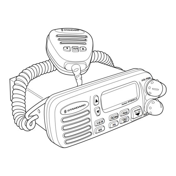
Page 8: Controls And Indicators
CONTROLS AND INDICATORS NOTE This section defines each control of the transceiver. See Figure 1 for location of controls. For detailed operating instructions refer to chapter 4 of this manual. 3.1 CONTROLS AND CONNECTIONS q POWER SWITCH/VOLUME CONTROL Turns the transceiver on and off as well as adjusts the audio volume. To turn the transceiver on press and hold this knob until the LCD turns on. - Page 9 VOL/PWR 16/9 SCAN DISTRESS PULL OPEN CALL /SET 16/9 Figure 1. Controls and Connectors GX1265S Owner’s Manual page 6...
- Page 10 WX Key Immediately recalls the previously selected NOAA weather channel from any channel location. Secondary use 1. Holding down the 16/9 key while pressing the WX key changes the mode from USA to International or Canadian. 2. Holding down the WX and SCAN key while turning the power on resets the microprocessor and erases scan channels from memory.
- Page 11 POS key Press the POS key, when connected to a GPS receiver, to displays position data (LAT/LON) on the LCD. r ACCESSORY CONNECTION CABLE Connects the radio to a GPS and an external speaker. t DC INPUT CABLE Connects the radio to a DC power supply of 13.8V ± 20%. y ANTENNA JACK Connects an antenna to the transceiver.
-
Page 12: Installation
INSTALLATION 4.1 LOCATION The radio can be mounted at any angle. Choose a mounting location that: • is far enough from any compass to avoid any deviation in compass reading due to the speaker magnet • provides accessibility to the front panel controls •... -
Page 13: Accessory Cable
2. Connect the red power wire to a 13.8 VDC ± 20% power source. Connect the black power wire to a negative ground. 3. If an optional remote extension speaker is to be used, refer to section 4.3 for connections. 4. -
Page 14: Cmb16 Flush Mount Installation
4.4 CMB16 FLUSH MOUNT INSTALLATION 1. Make a rectangular template for the flush mount measuring 2 1/8" H x 5 3/4" W. 2. Use the template to mark the location where the rectangular hole is to be cut. Confirm the space behind the dash or panel is deep enough to accommodate the transceiver (at least 6 inches deep). -
Page 15: Basic Operation
BASIC OPERATION 5.1 RECEPTION 1. After the transceiver has been installed, ensure that the power supply and antenna are properly connected. 2. Press and hold the VOL/PWR knob until the radio turns on. 3. Turn the SQL knob fully counterclockwise. This state is known as “squelch off”. -
Page 16: Transmit Time - Out Timer (Tot)
5.3 TRANSMIT TIME - OUT TIMER (TOT) When the PTT switch on the microphone is held down, transmit time is limited to 5 minutes. This prevents unintentional transmissions. About 10 seconds before automatic transmitter shutdown, a warning beep will be heard from the speaker(s). -
Page 17: Noaa Weather Channels
5.6 NOAA WEATHER CHANNELS 1. To receive a weather channel, press the WX key from any channel. The transceiver will go to the last selected weather channel. 2. Press the UP or DOWN key on the transceiver or microphone to select a different weather channel. -
Page 18: Memory Scanning
5.8 MEMORY SCANNING NOTE • During scanning, the dot matrix area of the LCD will show MEM- SCAN or PRI-SCAN depending on the scan mode selected. • The channel number shown is the last channel that a transmission was received on. 1. -
Page 19: Position Indication
5.10 POSITION INDICATION The transceiver has the ability to display the time and date as well as the vessel’s position (LAT/LON), if connected to a GPS receiver. 1. Press the POS key to display position JUN15 08:45P information. 35.55. 138.28. 2. -
Page 20: Digital Selective Calling
DIGITAL SELECTIVE CALLING 6.1 GENERAL 6.1.1 Digital Selective Calling (DSC) Digital Selective Calling is a semi-automated method of establishing a radio call, it has been designated by the International Maritime Organization (IMO) as an international standard for establishing VHF, MF and HF radio calls. -
Page 21: Sending A Distress Call
6.2 SENDING A DISTRESS CALL The distress call automatically includes the vessel’s DSC MMSI and Lat/ Lon position. Refer to section 7.7, USER MMSI INPUT. The vessel’s position can be sent only if the transceiver is properly connected to an operating navigation receiver. -
Page 22: Sending An Individual Call
6.3 SENDING AN INDIVIDUAL CALL To send an individual call, see section 7.4 INDIVIDUAL DIRECTORY SETUP. The individual call function allows you to transmit a DSC signal to a specific party only, prompting communication on a voice channel. 1. Select the traffic channel for voice communica- HI USA tion. -
Page 23: Sending An All Ships Call
10. When an individual call acknowledgment with UNATTENED “unable to comply” is received, the established >SEND EXIT channel is automatically selected. 11. To cancel, select EXIT using the DOWN key and press the CALL/ SET key. This procedure can be also canceled as follows; Press the CALL/SET key or 16/9 key. -
Page 24: Dsc Standby
6.5 DSC STANDBY The DSC Standby function allows the transceiver to reply to DSC calls with the UNATTENDED message and log the calls for return at a more convenient time. When set to the DSC Standby mode, voice traffic may still be monitored on any selected channel. -
Page 25: Operation Of Distress Call Waiting
6.6.1 Operation of Distress Call Waiting 1. Press the CALL/SET key. >INDIVIDUAL ALL SHIP The DSC CALLING menu will appear. STANDBY CALL WAIT 2. Press the UP or DOWN key to select CALL INDIVIDUAL ALL SHIP WAIT. STANDBY >CALL WAIT 3. -
Page 26: Receiving Dsc Calls
6. Press the UP or DOWN key to select the name. >NAME1 NAME2 NAME3 NAME4 7. Press the CALL/SET key to display the logged JUN15 08:45P ID987654321 call. >SEND EXIT 8. Press the CALL/SET key to resend the INDIVIDUAL CALL. 9. -
Page 27: Receiving An All Ships Call
NOTE You must continue monitoring channel 16 as a coast station may require assistance in any rescue attempt. 6.7.3 Receiving an all ships call 1. An all ships call is received. An emergency ALL SHIPS ID366911111 alarm sounds. JUN15 07:00P Then channel 16 is automatically selected. -
Page 28: Dsc / Radio Setup Mode
DSC / RADIO SETUP MODE 7.1 SETUP 1. Press and hold down the CALL/SET key until >LAMP ADJUST CONTRAST the SETUP menu appears. INDIV DIR KEY BEEP 2. To select the items, press the UP or DOWN key. 7.2 LAMP ADJUSTING 1. -
Page 29: Individual Directory Setup (Dsc)
7.4 INDIVIDUAL DIRECTORY SETUP (DSC) 1. Press and hold the CALL/SET key until the LAMP ADJUST CONTRAST SETUP menu is displayed. >INDIV DIR KEY BEEP 2. Select INDIVI DIR by using the UP or DOWN key. 3. Press the CALL/SET key to enter the individual N A M E –... -
Page 30: Key Beep (On Or Off)
11. To enter another individual address select NEXT with the UP or DOWN key and press the CALL/SET key. Repeat steps 4 through 10. 12. To exit the individual directory setup, select EXIT with the UP or DOWN key and press the CALL/SET key. NOTE Selecting NEXT or EXIT will automatically save the name and MMSID number into memory. -
Page 31: User Mmsid Input
2. Press the CALL/SET key. TIME SET 00 : 00 The time offset menu appears. 3. Press the UP or DOWN key to select time offset TIME SET –08 : 00 from UTC. See Figure 4 to find your offset time from UTC. If 00:00 is assigned, the time is the same as UTC (Universal Time Coordinated) or GMT (Greenwich Mean Time) -
Page 32: Dsc Scan
3. Press the UP or DOWN key to set the number USER MMSID 0 – – – – – – – (0 to 9 ). 4. Press the CALL/SET key to store the set USER MMSID 0 – – – – – – – number. -
Page 33: Maintenance
8.1 REPLACEMENT PARTS Occasionally an owner needs a replacement mounting bracket or knob. These can be ordered from our Parts Department by writing or calling: STANDARD HORIZON, a division of VERTEX STANDARD. 17210 Edwards Rd., Cerritos, CA 90703, U.S.A. (562)404-2700 Commonly requested parts, and their part numbers are listed below. -
Page 34: Troubleshooting Chart
If the fuse still blows, contact your STANDARD HORIZON Dealer. Engine noise. Popping or whining noise Reroute the DC power cables away from the speaker while f r o m t h e e n g i n e . -
Page 35: Specifications
SPECIFICATIONS Performance specifications are nominal, unless otherwise indicated, and are subject to change without notice. 9.1 GENERAL Channels ........... All USA, International and Canadian Input Voltage ..............13.8 VDC +/-20% Current Drain Standby ..................0.5A Receive ..................1.5A Transmit ..............6A (Hi); 1.7A (Lo) Dimensions ............ - Page 36 Marine Division of Vertex Standard US Headquarters 17210 Edwards Rd., Cerritos, CA 90703 Phone 562/404-2700 Fax 800/552/6813 Email marinetech@vxstd.com www.vxstd.com Printed in China 00/12 456X851012...
Need help?
Do you have a question about the Intrepid LE GX1265S and is the answer not in the manual?
Questions and answers