NAPCO Gemini GEM-P1664EX Programming R Instructions
Control panel/communicator
Hide thumbs
Also See for Gemini GEM-P1664EX:
- Datasheet (2 pages) ,
- Programming instructions manual (64 pages)
Table of Contents
Advertisement
Quick Links
Publicly traded on NASDAQ
Symbol: NSSC
HARDWIRE
CONTROL PANEL/COMMUNICATOR
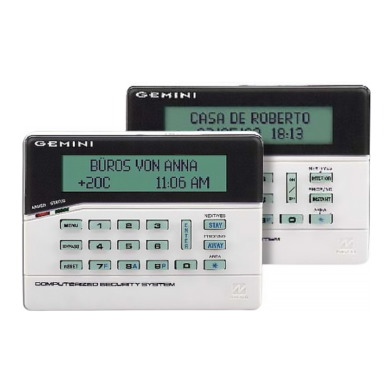
"Classic" GEM-RP1CAe2 Keypad and the "K Series" GEM-K1CA Keypad
G E M I N I
SYSTEM READY
01/01/05
A
1
B
4
C
7
C O M P U T E R I Z E D S E C U R I T Y S Y S T E M
"Classic" GEM-RP1CAe2
Quick Start (for "Classic" GEM-RP1CAe2)
1. Refer to the wiring diagram, connect Siren, Aux. Power,
PGM Output, Remote Bus, Earth ground, Zone and Tele-
phone wiring.
NOTE:
(WI1388).
2. Connect AC power first and then the battery.
3. Configure the keypad (see page 42).
4. Access the Easy Menu Driven (Dealer Program) Mode:
Press
456789 A
Dealer Code
Press NO (
) until "ACTIVATE PROGRAM Y/N" appears on the
g
keypad display.
Press YES (
) to Enter Dealer Program Mode. Go to page 5.
F
© NAPCO 2005
R
G E M - P 1 6 6 4 E X
Programming the GEM-P1664EX Control Panel with the
12:00 AM
NEXT/YES
D
2
3
E
PRIOR/NO
F
5
6
AREA
8
9 0
G
See Installation Instructions
PROGRAMMING
INSTRUCTIONS
G E M I N I
C O M P U T E R I Z E D S E C U R I T Y S Y S T E M
Quick Start (for "K-Series" GEM-K1CA)
1. Refer to the wiring diagram, connect Siren, Aux. Power,
PGM Output, Remote Bus, Earth ground, Zone and Tele-
phone wiring.
(WI1388).
2. Connect AC power first and then the battery.
3. Configure the keypad (see page 42).
4. Access the Easy Menu Driven (Dealer Program) Mode:
Press
456789 R
Press NO (
Q
keypad display.
Press YES (
P
WIRELESS
SYSTEM READY
01/01/05
12:00 AM
U
R
1
2
3
B
4
5
6
C
7
8
9 0
"K Series" GEM-K1CA
NOTE:
See Installation Instructions
Dealer Code
) until "ACTIVATE PROGRAM Y/N" appears on the
) to Enter Dealer Program Mode. Go to page 5.
NEXT/YES
P
PRIOR/NO
Q
AREA
G
WI1386 5/05
Advertisement
Table of Contents

Related Manuals for NAPCO Gemini GEM-P1664EX


Summary of Contents for NAPCO Gemini GEM-P1664EX
- Page 1 ) until “ACTIVATE PROGRAM Y/N” appears on the keypad display. keypad display. Press YES ( ) to Enter Dealer Program Mode. Go to page 5. Press YES ( ) to Enter Dealer Program Mode. Go to page 5. © NAPCO 2005 WI1386 5/05...
-
Page 2: Important Note
CONTROL PANEL FIRMWARE VERSION 1.0 OR LATER. IMPORTANT NOTE This manual supports the keypad programming of the GEM-P1664EX control panel with the NAPCO "classic" GEM- RP1CAe2 keypad as well as the GEM-K1CA "K Series" keypad. The new "K Series" GEM-K1CA model offers the new STAY and AWAY buttons with simplified functionality, along with the new MENU and ENTER buttons. -
Page 3: Table Of Contents
GEM-P1664EX WIRING DIAGRAM ........ 60 Direct Address Overview ..........11 Address Mode Displays ..........11 Binary (Bit) Format ..........11 Decimal Format ..........12 Hexadecimal Format .......... 13 Refer to accompanying GEM-P1664EX Installation Instructions (WI1388) for installation information. NAPCO Security Systems GEM-P1664EX Programming Instructions... -
Page 4: System Programming Options
For direct high-speed data transfer to the control panel from a desktop computer, connect the download jack (JP2) on the panel to the LOCAL jack (J3) on the Napco PCI2000/3000 computer interface using the supplied 6- conductor cable. (Refer to PCI2000/3000 Installation Instructions WI443 for wiring diagram and procedures). -
Page 5: Easy Menu Driven Program Mode
Should it be necessary to create a new custom default pro- gram, (a) from the Dealer Program Mode, press the button to enter the Direct Address Program Mode; (b) access Location 2285 (Clear Program); (c) press the button and start over. NAPCO Security Systems GEM-P1664EX Programming Instructions... -
Page 6: Gem-Rp1Cae2/Gem-K1Ca Easy Program Menu
Valid entries are from 01 to 64. Directly enter each zone number, including leading zeros. • Press to save and repeat for any additional zone(s); press the NEXT/YES button to proceed. (Direct Entry) NOTE: 24 Hour Zones will automatically be programmed as audible (Burg Output). NAPCO Security Systems GEM-P1664EX Programming Instructions... -
Page 7: Chime Zones In Area 1
Press YES to enable Telco Line Fault Test. Enable Telco • Line Test? Press NO to continue. NOTE: If enabled, a Telco Line Fault Test Delay of 60 sec. will auto- matically be programmed. (Press YES or NO) NAPCO Security Systems GEM-P1664EX Programming Instructions... -
Page 8: Enable Burg Output Chirp On Keyfob
Ambush “User Program”. Enter “2222” for a user code, blank(•) Add 8 * User Program “• (blank) 9” for area 1 options and “• (blank) • blank(•) Bypass Enable (blank)” for area 2 options. NAPCO Security Systems GEM-P1664EX Programming Instructions... -
Page 9: Rf Transmitter Points
NEXT/YES button to proceed when all key fobs have been entered. NOTE: When programming the ID Code number, “0” through ”9” = through ; A = ; B = ; D = ; E = and “F” = NAPCO Security Systems GEM-P1664EX Programming Instructions... -
Page 10: Key Fob Transmitters As Zone Input Devices
Program new description as above. NOTE: Zone Descriptions can only be en- tered through the GEM-RP1CAe2 Keypad or by using the Napco Quickloader Software. See Easy Menu Programming Work- sheet for available zone description characters. -
Page 11: Direct Address Program Mode
"bit numbers" 1,3,4 and 6, respec- tively. DETERMINE THE DATA ENTRIES 1. Referring to ZONE FEATURES in the Programming Worksheets that follow, the Exit/Entry Follower for Zones 1 through 8 are located at address 0916. NAPCO Security Systems GEM-P1664EX Programming Instructions... -
Page 12: Decimal Format
2. Answer NO to all questions until “ACTIVATE PROGRAM Y/N” is displayed; then press YES. NOTE: If you pass “ACTIVATE PROGRAM”, scroll backward using 3. Press to enter the Address Program Mode. Address "0000" will display. 4. Press to access Address 1417. The existing data will display and the cursor will 1417 NAPCO Security Systems GEM-P1664EX Programming Instructions... -
Page 13: Hexadecimal Format
(•) ¼sec. = 1 sec. blank (•) ¼sec. = 1.25 sec. blank (•) ¼sec. = 1.5 sec. blank (•) ¼sec. = 1.75 sec. 2 seconds blank (•) ¼sec. = 2 sec. ¼sec. = 63.25 NAPCO Security Systems GEM-P1664EX Programming Instructions... -
Page 14: Programming Conventions Used In This Manual
It is recom- mended that the panel be uploaded to NAPCO's PCD-Windows software following any keypad programming and that the PCD-Windows's error-check feature be utilized to reduce the possibility of programming omissions or conflicts. -
Page 15: System Delays & Timeouts
1. Enter delay/timeout in corresponding address locations above. Note: All entries for address 1418 are in quarter seconds (.25 seconds). Therefore, the default of 008 results in a 2 second timeout. 2. Press to save. NAPCO Security Systems GEM-P1664EX Programming Instructions... -
Page 16: System Output Timeouts
Pager report will now appear as “983 22 1234”. NOTE: See CS Receiver Options to select Pager Format. Leading Digits for Pager Format 1. Enter in 1st and 2nd Leading Digits as shown (right nibble). (2nd Digit) 2. Valid entries are: 0-9. Press to save. [Default = blank (•) blank (•)] NAPCO Security Systems GEM-P1664EX Programming Instructions... -
Page 17: System Options
(•), then the 2-digit Global Ambush Code is the two digits entered in address 2045. [Default = blank (•) blank (•)] Enter in address location (both 1st and 2nd digits); valid entries are 1-9. Press to save. NAPCO Security Systems GEM-P1664EX Programming Instructions... - Page 18 1. Select the desired option entering the option number (1-8) for each digit. 2. Enter corresponding option number in address location. NOTE: Dark shaded data value box shows option not available. Press to save. NAPCO Security Systems GEM-P1664EX Programming Instructions...
- Page 19 Enable EN501 Grade 3 Operation ****Note: If this feature is not selected, the E15 Lug will, by default, RESERVED activate when the system is armed (all areas). Enable 2-Count Swinger Shutdown Enable Keypad Blanking NAPCO Security Systems GEM-P1664EX Programming Instructions...
-
Page 20: Cs Receiver Options
2. Enter up to 20 digits from left to right. NOTE: Leave trailing boxes blank (•). Press [Enter] or [ON/OFF] to save. 3. Valid entries are: 1-9, B = button, C = button, D = 3 sec. pause, E = Wait for dial tone, F = Ignore location NAPCO Security Systems GEM-P1664EX Programming Instructions... -
Page 21: Cs Subscriber Id Options
1. Enter 3 or 4 digits (depending on the CS receiver format) for each subscriber number from left to right. NOTE: Leave trailing boxes blank (•). 2. Valid entries are: 1-9, 0 and B-F. NOTE: A is not permitted. Press [Enter] or ON/OFF] to save. NAPCO Security Systems GEM-P1664EX Programming Instructions... -
Page 22: Cs System Reporting Options
Disable Wait for Handshake on Transmit * NOTE: If neither Touch-tone Dialing nor Touch-tone w/Rotary Disable Auto Dial Tone Detect Backup is selected, then system defaults automatically to Rotary Dialing. Leave blank (•) to select Rotary Dialing. NAPCO Security Systems GEM-P1664EX Programming Instructions... -
Page 23: Zone Anding Time Window
Clock Source (Internal Panel )* address location. Line Frequency--Enable 50Hz ** NOTE: Dark shaded rows indicate option not avail- RESERVED able. RESERVED Press to save. RESERVED RESERVED RESERVED *[Default = AC Source used] **[Default = 60Hz] NAPCO Security Systems GEM-P1664EX Programming Instructions... -
Page 24: Cs Zone Reporting Options
MODEM CODES determine the zone types reported for the following formats: SIA and ADEMCO Point ID. Gas Alarm 1. Select the desired Modem Code for each zone from the table shown. Heat Alarm Auxiliary Alarm 2. Press to save. 24 Hour Auxiliary NAPCO Security Systems GEM-P1664EX Programming Instructions... -
Page 25: Cs User Reporting Options
Select the desired option entering the option number (1-8) for each digit. At the keypad, enter corresponding option number in address location. NOTE: Dark shaded data value box shows option not available. Press to save. NAPCO Security Systems GEM-P1664EX Programming Instructions... -
Page 26: Ezm Group Options
2. Enter either blank (•) or "1" in corresponding address locations 29-32 37-40 4-Zone EZM 33-36 41-44 above. 37-40 45-48 41-44 49-52 NOTE: Dark shaded data value box shows option not available. 45-48 53-56 3. Press to save. 49-52 57-60 53-56 61-64 57-60 61-64 NAPCO Security Systems GEM-P1664EX Programming Instructions... -
Page 27: Area Bell Control Options
(1,2,3,4) accordingly. For example, if you wish to grant an Area 1 keypad the ability to turn off an Area 2 PGM2 output, enter "2" in Address 1485. Enter digit in address location. NOTE: Dark shaded data value box shows option not available. Press to save. NAPCO Security Systems GEM-P1664EX Programming Instructions... -
Page 28: Keypad Options
Select the desired option entering the option number (1-8) for each digit. At the keypad, enter corresponding option number in address location. NOTE: Dark shaded data value box shows option not available. Press to save. NAPCO Security Systems GEM-P1664EX Programming Instructions... -
Page 29: Temperature Display At Keypad
140F (or -30C to 60C). Fahrenheit is the default setting, select Celsius by enabling address 1668 option 2. When this Tempera- ture Display Option is enabled, Zone 6 becomes the input for the “Napco Temperature Sensor” module and Zone 6 of the panel becomes inoperative;... -
Page 30: Area Arming Options
50 or 750 ms as selected by jumpers on the EZM. In addition, zone responses are enabled only when armed. 1. Enter digit only. 2. Valid entries are: 001-750. NOTE: Default is 750ms (075 x 10ms). 3. Press to save. NAPCO Security Systems GEM-P1664EX Programming Instructions... -
Page 31: Zone Options - Zones 1 To 16
Select the desired zone option by entering the option number (1-8) for each selected zone. located on the bottom Enter corresponding option number in address location. of the next page. NOTE: Dark shaded data value box shows option not available. Press [Enter] or ON/OFF] to save. NAPCO Security Systems GEM-P1664EX Programming Instructions... -
Page 32: Zone Options - Zones 17 To 32
Pulse Alarm Output is enabled for the zone number(s) entered in “FIRE ZONES ENTER ZONE #” or “2-WIRE FIRE ZNS ENTER ZONE #”. • Fire is enabled for the zone number(s) entered in “FIRE ZONES ENTER ZONE #”. • 2-Wire Smoke Detector is enabled for the zone number(s) entered in “2-WIRE FIRE ZNS ENTER ZONE #”. NAPCO Security Systems GEM-P1664EX Programming Instructions... -
Page 33: Zone Options - Zones 33 To 48
Select the desired zone option by entering the option number (1-8) for each selected zone. Enter corresponding option number in address location. NOTE: Dark shaded data value box shows option not available. Press [Enter] or ON/OFF] to save. NAPCO Security Systems GEM-P1664EX Programming Instructions... -
Page 34: Zone Options - Zones 49 To 64
Pulse Alarm Output is enabled for the zone number(s) entered in “FIRE ZONES ENTER ZONE #” or “2-WIRE FIRE ZNS ENTER ZONE #”. Fire is enabled for the zone number(s) entered in “FIRE ZONES ENTER ZONE #”. 2-Wire Smoke Detector is enabled for the zone number(s) entered in “2-WIRE FIRE ZNS ENTER ZONE #”. NAPCO Security Systems GEM-P1664EX Programming Instructions... -
Page 35: External Relay Control
1646 1647 1648 1639 1640 1641 1642 1643 RELAY # AREA TIMEOUT EVENT ID COND. RELAY # AREA TIMEOUT EVENT ID COND. TO PROGRAM, SEE NEXT PAGE [Default = blank (•) from address 1489-1648]. NAPCO Security Systems GEM-P1664EX Programming Instructions... - Page 36 5A. Select Alarm Type and Timeout Type from Table 5A (on next page); enter in corresponding left address location. 5B. Select Activation Conditions from Table 5B (on next page); enter in corresponding right address location. Continued NAPCO Security Systems GEM-P1664EX Programming Instructions...
- Page 37 Relay Control Group 2 Area 2 Fail to Open Zone 36 Entry Relay Area 1 Area 2 Fail to Close Zone 37 Entry Relay Area 2 Entry Relay Area 3 Entry Relay Area 4 NAPCO Security Systems GEM-P1664EX Programming Instructions...
-
Page 38: Rf Receiver & Supervisory Timer Options
Type E Smoke Detector 2043 Type F Napco Glass Break 2044 [Default = blank (•) from address 2029-2044]. Default = 8 (240 minutes) NOTE: These timers apply only to Supervised RF Transmitters (see RF Transmitters in Easy Menu Driven Mode Programming). -
Page 39: Clear Program Options
User Program Mode. NOTE: For ease of programming, it is recommended that a GEM K1CA (or GEM-RP1CAe2) be used. See Keypad Configuration Mode. If a GEM-RP2ASe2/GEM-K2AS keypad is used, see WI1387. NAPCO Security Systems GEM-P1664EX Programming Instructions... -
Page 40: Accessing User Program Mode
Enter the new User Code using the number buttons (0-9). If an old code is displayed, program over it. To erase the digit at the cursor, press button. Press the button to save the code in memory. Repeat this procedure for each user. To proceed to Zone-Description programming, press the NEXT button or the PRIOR but- ton. NAPCO Security Systems GEM-P1664EX Programming Instructions... -
Page 41: Zone Descriptions
MM=minutes (00–59). Select AM or PM by pressing any number button, then press (Direct Entry) once again to save. NOTE: To enter the date and time, GEM-RP1CAe2/GEM-K1CA keypad (version 9A or greater) must be used and “Enable Keypad Time/Date Display” (Address 1420) must be enabled. NAPCO Security Systems GEM-P1664EX Programming Instructions... -
Page 42: Keypad Configuration Mode
1. Enter the assigned keypad number 01–07, then press to save. A valid number will be acknowledged by a short beep; an invalid number will be rejected by a long beep. 2. Press to continue or press to exit. NAPCO Security Systems GEM-P1664EX Programming Instructions... - Page 43 (the display will loop back through selections, for changes) or press the button to exit the Key- 01 OUT OF SYSTEM pad Configuration Mode (display will read “ ”). Then replace Jumper JP1 across Pins 1–2 (top two). NAPCO Security Systems GEM-P1664EX Programming Instructions...
-
Page 44: Easy Menu Programming Worksheets
Page 44 WI1386 5/05 EASY MENU PROGRAMMING WORKSHEET - 1 OF 4 NAPCO Security Systems GEM-P1664EX Programming Instructions... - Page 45 RF ID CHECK POINT XMTR # ZONE RF ID CHECK POINT (printed on xmtr box) (printed on xmtr box) KEY FOB # Area RF ID CHECK OPTION OPTION Key Fob Transmitters: (printed on xmtr box) NAPCO Security Systems GEM-P1664EX Programming Instructions...
- Page 46 A B C D E F G H I J K L M N O P Q R S T U V W X Y For Zones 33-64, see next page Dealer Code: NAPCO Security Systems GEM-P1664EX Programming Instructions...
- Page 47 A B C D E F G H I J K L M N O P Q R S T U V W X Y For Zones 1-32, see previous Dealer Code: page NAPCO Security Systems GEM-P1664EX Programming Instructions...
-
Page 48: Alphabetical Index
AUTO BYPASS RE-ENTRY ZONES ................7 CS SYSTEM REPORTING CODES (ADDRESS 0683-0708) ........22 AUTO RESET AFTER BURGLARY OUTPUT TIMEOUT ...........19 CS SYSTEM REPORTING OPTIONS ................ 22 AUTO RESET--ZONE OPTION ..............31, 32, 33, 34 NAPCO Security Systems GEM-P1664EX Programming Instructions... - Page 49 ENABLE CP-01 EGRESS TONES ONLY ..............19 ENABLE CP-01 LIMITS ....................19 ENABLE DAYLIGHT SAVING TIME ................23 ENABLE DISPLAY TIME ON BLANKED KEYPADS ..........19 ENABLE EN501 GRADE 3 OPERATION ..............19 GAS ALARM MODEM CODE ..................24 NAPCO Security Systems GEM-P1664EX Programming Instructions...
- Page 50 LOW BATTERY (ADDRESS 0686) ................22 PROGRAMMING OPTIONS ..................4 LUG E15 AREA 1 ARMED AWAY ONLY ..............19 PROGRAMMING OVERVIEW ..................4 PROGRAMMING STEPS - GENERAL ............... 14 PULSE ALARM OUTPUT (ADDRESS 1415) ............. 16 NAPCO Security Systems GEM-P1664EX Programming Instructions...
- Page 51 SUM CHECK .........................20 USER AREA OPTIONS ....................8 SUPPRESS BYPASS REMINDER WHEN ARMED ...........19 USER CODES - PROGRAMMING ................40 SWINGER SHUTDOWN--ZONE OPTION ..........31, 32, 33, 34 USER CODES--CHANGING OR CANCELING ............9 NAPCO Security Systems GEM-P1664EX Programming Instructions...
- Page 52 ZONE OPTIONS - ZONES 17 TO 32 (ADDRESS 1029-1144) ........32 ZONE OPTIONS - ZONES 33 TO 48 (ADDRESS 1157-1272) ........33 ZONE OPTIONS - ZONES 49 TO 64 (ADDRESS 1285-1400) ........34 ZONE RESPONSE .......................43 ZONE RESPONSE TIME (ADDRESS 2062) ..............30 NAPCO Security Systems GEM-P1664EX Programming Instructions...
-
Page 53: Address Number Index
(ADDRESS 0786) ............REPORTING OPTIONS ..........22 (ADDRESS 0786) ............SYSTEM REPORTING OPTIONS ........22 (ADDRESS 0788) ............CS AREA & SYSTEM REPORTING OPTIONS ....22 (ADDRESS 0788) ............CS SYSTEM REPORT OPTIONS ........22 NAPCO Security Systems GEM-P1664EX Programming Instructions... - Page 54 (ADDRESS 1418) ............CHIME ADDRESS TIME ..........15 (ADDRESS 1418-1419) ..........SYSTEM DELAYS & TIMEOUTS ........15 (ADDRESS 1419) ............AC FAIL REPORT DELAY ..........15 (ADDRESS 1420) ............SYSTEM OPTIONS ............19 (ADDRESS 1421) ............SYSTEM OPTIONS ............19 NAPCO Security Systems GEM-P1664EX Programming Instructions...
- Page 55 (ADDRESS 2062) ............ZONE INTEGRATION TIME ..........30 (ADDRESS 2062) ............ZONE RESPONSE TIME ..........30 (ADDRESS 2281) ............CLOCK ADJUSTMENTS ..........23 (ADDRESS 2285) ............ERASING DEALER PROGRAM ........39 (ADDRESS 2286) ............COLD START ..............39 NAPCO Security Systems GEM-P1664EX Programming Instructions...
-
Page 56: Gem-P1664Ex Wiring Diagram
Page 56 WI1386 5/05 GEM-P1664EX WIRING DIAGRAM NAPCO Security Systems GEM-P1664EX Programming Instructions...
Need help?
Do you have a question about the Gemini GEM-P1664EX and is the answer not in the manual?
Questions and answers