
Related Manuals for RadiSys PROCELERANT SB5520DT1-SATA


Summary of Contents for RadiSys PROCELERANT SB5520DT1-SATA
- Page 1 PROCELERANT ® SB5520DT1 MOTHERBOARD PRODUCT MANUAL SB5520DT1-SATA SB5520DT1-SAS www.radisys.com 007-03344-0000 • October 2010...
- Page 2 © 2010 by RadiSys Corporation. All rights reserved. RadiSys and Procelerant are registered trademarks of RadiSys Corporation. Intel is a registered trademark of Intel Corporation. Microsoft, Windows, and Windows XP are registered trademarks of Microsoft Corporation. Red Hat and Red Hat Linux are registered trademarks of Red Hat, Inc.
-
Page 3: Table Of Contents
TABLE OF CONTENTS Preface ................................7 About this manual..................................7 Safety notices....................................7 Electrostatic discharge....................................7 Lithium cell battery....................................8 Where to get more product information ..........................8 Chapter 1: Introduction ............................ 9 Product models .......................................9 Board layout ....................................10 General specifications..................................12 Chipset overview .................................. - Page 4 Table of Contents Chapter 2: Hardware Reference........................19 Control panel connectors/IO ports ............................19 Back panel connectors/IO ports ............................... 19 Headers and connectors................................21 Front control panel JF1 header................................. 21 Power connectors ....................................24 Fan headers......................................25 Chassis intrusion ....................................25 Power LED/speaker .....................................
- Page 5 Table of Contents Chapter 3: BIOS Configuration ........................37 Starting the BIOS setup utility..............................37 About the setup utility ..................................37 Main menu ....................................38 Advanced menu..................................39 Security menu ....................................59 Boot menu....................................61 Exit menu ....................................62 BIOS recovery .................................... 63 How to recover the AMIBIOS image ...............................
- Page 6 Table of Contents...
-
Page 7: Preface
PREFACE About this manual This manual describes the RadiSys Procelerant SB5520DT1 motherboard. This manual is ® intended for professional technicians, system integrators, and knowledgeable personal computer users. The manual is organized as follows: Chapter 1, Introduction, on page 9 describes the features, specifications, and performance ... -
Page 8: Lithium Cell Battery
Keep the battery away from children. Where to get more product information For additional product information, visit the Embedded Server product pages on the RadiSys Web site at www.radisys.com for access to datasheets, product documentation, BIOS releases, and drivers. -
Page 9: Chapter 1: Introduction
Integrated video controller to provide management/configuration console display Contact your RadiSys representative for updates on supported or recommended processors. Product models The SB5520DT1 motherboard is available in two models: SB5520DT1-SAS and SB5520DT1-SATA. The two models are almost identical, except that the SB5520DT1-SAS model includes a SAS 2.0 controller on the motherboard. -
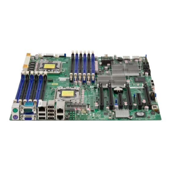
Page 10: Board Layout
Introduction Board layout Figure 1. SB5520DT1 layout: top view POST CODE LEDs LAN2 IPMI LAN MOUSE LAN CTRL FAN5 COM1 FAN8 USB0/1 FAN6 LAN1 (not populated on JI2C2 SB5520DT1-SAS) Jl2C1 JPL1 JSMB1 JPG1 JPB1 CPU2 BIOS Battery USB7 USB6 JBT1 Intel 5520 (IOH-36D-2) Intel ICH10R... - Page 11 Board layout To prevent damage to the power supply or motherboard, use a power supply ARNING that contains a 24-pin and two 8-pin power connectors. Be sure to connect these connectors to the 24-pin (JPW1) and the two 8-pin (JPW2 and JPW3) power connectors on the motherboard.
-
Page 12: General Specifications
Introduction Table 4. LED Description Onboard standby power LED indicator (power LED) BMC activity LED indicator LEDS2 SAS heartbeat LED indicator: green (SB5520DT1-SAS only) LEDS2 SAS error LED indicator: red (SB5520DT1-SAS only) General specifications Table 5. SB5520DT1 specifications Item Description Two Intel 5500/5600 series (LGA 1366) processors. - Page 13 Board layout Table 5. SB5520DT1 specifications Item Description ACPI features Slow blinking LED for suspend state indicator Main switch override mechanism ACPI Power Management Onboard I/O Intel ICH10R supports six SATA2 ports (with RAID0, RAID1, RAID10, RAID5 sup- ported in the Windows OS Environment and RAID0, RAID1, RAID10 supported in the Linux OS) Intel 82576 Gigabit Ethernet controller supports dual Giga-bit LAN ports...
- Page 14 Introduction Figure 2. Block diagram...
-
Page 15: Chipset Overview
Chipset overview Figure 3. Processor and slot positions Chipset overview Built on the Intel 5500/5600 series processor and the 5520 chipset, the SB5520DT1 motherboard provides the performance and feature set required for dual-processor-based high- end systems that are optimized for high-performance computing (HPC) and clustering servers. The SB5520DT1 chipset consists of dual 5520 IO hubs and an ICH10R (South Bridge). -
Page 16: Main Features Of The 5500/5600 Series Processor And The 5520 Chipset
Introduction Each Intel 5520 supports up to 36 PCI Express Gen2 lanes with peer-to-peer read and write transactions. The ICH10R provides up six SATA ports and 10 USB connections. In addition, the SB5520DT1 chipset also offers a wide range of RAS (Reliability, Availability and Serviceability) features. -
Page 17: Environmental Temperature Control
ACPI features Environmental temperature control The thermal control sensor monitors the CPU temperature in real time and turns on the thermal control fan whenever the CPU temperature exceeds a user-defined threshold. The overheat circuitry runs independently from the CPU. Once the sensor detects that the CPU temperature is too high, it automatically turns on the thermal fan control to prevent any overheat damage to the CPU. -
Page 18: Power Supply
Introduction Power supply As with all computer products, a stable power source is necessary for proper and reliable operation. It is even more important for processors that have high CPU clock rates. The SB5520DT1 can accommodate 24-pin ATX power supplies. Although many power supplies generally meet the specifications required by the CPU, some are inadequate. -
Page 19: Chapter 2: Hardware Reference
HARDWARE REFERENCE This chapter describes the hardware components of the SB5520DT1 motherboard. For the location of each component on the motherboard, refer to Board layout on page Control panel connectors/IO ports The I/O ports are color coded in conformance with the PC 99 specification. See the picture below for the colors and locations of the various I/O ports. -
Page 20: Video Connector
Hardware Reference Serial ports Two COM connections (COM1 & COM2) are located on the motherboard. COM1 is located on the backplane IO panel to provide serial connection support for the motherboard. Table 7. Serial port pin definitions Pin # Definition Pin # Definition Ground... -
Page 21: Ethernet Ports
These connectors are designed specifically for use with RadiSys server chassis. See the figure below for the descriptions of the various control panel buttons and LED indicators. Refer to the following section for descriptions and pin definitions. -
Page 22: Nmi Button
Hardware Reference NMI button The non-maskable interrupt button header is located on pins 19 and 20 of JF1. Table 11. NMI button pin definitions (JF1) Pin # Definition Control Ground Power LED The power LED connection is located on pins 15 and 16 of JF1. Table 12. -
Page 23: Power Button
Headers and connectors Overheat (OH)/fan fail LED Connect an LED cable to the OH/fan fail connections on pins 7 and 8 of JF1 to provide advanced warnings for chassis overheat/fan failure. Table 15. OH/fan fail pin definitions (JF1) Pin # Definition OH/Fan Fail LED Table 16. -
Page 24: Power Connectors
Hardware Reference Power connectors A 24-pin main power supply connector (JPW1) and two 8-pin CPU PWR connectors (JPW2 and JPW3) on the motherboard. These power connectors meet the SSI EPS 12V specification. In addition to the 24-pin ATX power connector, the 12V 8-pin CPU PWR connectors at JPW2/JPW3 must also be connected to your power supply. -
Page 25: Fan Headers
Headers and connectors Fan headers This motherboard has eight CPU/system fan headers (Fan 1 to Fan 8) on the motherboard. All these 4-pin fans headers are backward compatible with the traditional 3-pin fans. However, fan speed control is available only for 4-pin fans. The fan speeds are controlled by the BIOS under Thermal Management. -
Page 26: Overheat Led/Fan Fail (Joh1)
Hardware Reference Overheat LED/fan fail (JOH1) The JOH1 header is used to connect an LED indicator to provide warnings of chassis overheating or fan failure. This LED will blink when a fan failure occurs. Table 25. Overheat LED pin definitions Pin # Definition +3.3V... -
Page 27: Power Smb (I 2 C) Connector
Jumper block settings Power SMB (I C) connector Power System Management Bus (I C) connector (JPI C) monitors power supply, fan status and system temperature. Table 29. PWR SMB pin definitions Pin # Definition Clock Data PWR Fail Ground +3.3V Jumper block settings Jumper shunts can be used to create shorts between two pins to change the function of the jumper block (header) on the motherboard. -
Page 28: Glan Enable/Disable
Hardware Reference GLAN enable/disable Use JPL1 to enable or disable GLAN port1/GLAN port2 on the motherboard. Table 30. GLAN Enable jumper settings Pin # Definition 1–2 Enabled (default) 2–3 Disabled CMOS clear JBT1 is used to clear CMOS. Instead of pins, this “jumper” consists of contact pads to prevent the accidental clearing of CMOS. -
Page 29: Sas Enable (Sb5520Dt1-Sas Only)
Onboard LED indicators SAS enable (SB5520DT1-SAS only) JPS1 allows you to enable or disable SAS connectors. The default position is on pins 1 and 2 to enable SAS. Table 33. SAS enable/disable jumper settings Jumper Setting Definition Pins 1–2 Enabled (default) Pins 2–3 Disabled Onboard LED indicators... -
Page 30: Bmc Activity Led
Hardware Reference BMC activity LED A BMC heartbeat LED is located at DP5 on the motherboard. When DP5 is blinking, BMC (Baseboard Management Controller) is active. In addition to DP5, there is a blue BMC Heartbeat LED visible from the rear of the chassis through the I/O panel. See the tables below for more information. -
Page 31: Rear I/O Post Code Leds
SATA and SAS connections Rear I/O POST code LEDs Eight POST code LEDs in a 4x2 array display the codes written to I/O location 80h during BIOS POST for diagnostic or debug support. The left column of 4 LEDs represents the upper four bits, and the right column of 4 LEDs represents the lower four bits;... -
Page 32: Processors And Heatsinks
When purchasing a motherboard without a 5500/5600 Series processor preinstalled, make sure that the CPU socket plastic cap is in place, and none of the CPU socket pins are bent; otherwise, contact your RadiSys representative immediately. Processor installation 1. Press the socket clip to unlock it. - Page 33 Processors and heatsinks 3. Lift and swing open the load plate. 4. Holding the plastic cap as shown, remove it from the CPU socket. 5. Holding the CPU between your thumb and index finger, align the CPU keys (the cutouts) with the socket keys.
- Page 34 Hardware Reference 6. Once the CPU and socket are aligned, carefully lower the CPU straight down into the socket. To avoid damaging the CPU or the socket, be careful not to rub the CPU ARNING against the surface of the socket or its pins. 7.
-
Page 35: Heatsink Installation
Processors and heatsinks Heatsink installation This procedure demonstrates how to install a passive heatsink. To install an active heatsink (“fansink”), plug the fan’s power connector into the nearest fan header after completing step 3. Refer to the board layout diagram on page 10 for fan header locations. -
Page 36: Heatsink Removal
Hardware Reference Heatsink removal Removal of the CPU or the heatsink is not recommended; however, if you do ARNING need to remove the heatsink, please follow these instructions to help prevent damage to the CPU and other components. 1. Unplug the power cord from the power supply. 2. -
Page 37: Chapter 3: Bios Configuration
Note: The AMI BIOS has default text messages built in. RadiSys retains the option to include, omit, or change any of these text messages. -
Page 38: Main Menu
Figure 8. Main menu BIOS SETUP UTILITY Main Advanced Security Boot Exit System Overview System Time [11:19:59] System Date [Thu 04/30/2009] RadiSys SB5520DT1 Version :1.0 Build Date :04/24/09 Processor Intel(R) Xeon(R) CPU E5530 @ 2.40GHz Speed :2400MHz Physical Count Logical Count... -
Page 39: Advanced Menu
Advanced menu Table 42. Main menu options BIOS item Usage System Memory Populated Size This item displays the installed memory size detected by the BIOS. Available Size This item displays the available memory detected by the BIOS. Advanced menu The Advanced menu displays a number of submenus. Use the up and down arrows to navigate the submenus;... -
Page 40: Boot Feature
BIOS Configuration BOOT feature Table 43. BOOT Feature submenu BIOS item Usage Quick Boot If enabled, this option skips certain tests during POST to reduce the time needed for system boot. The options are Enabled and Disabled. Quiet Boot This option allows the bootup screen options to be modified between POST messages or the OEM logo. -
Page 41: Processor And Clock Options
Advanced menu Processor and clock options Table 44. Processor & Clock Options submenu BIOS item Usage CPU Ratio If set to Manual, this option enables you to set the ratio between the CPU Core Clock and the FSB Frequency. The options are Auto and Manual. Note: If an invalid ratio is entered, the AMI BIOS will restore the setting to the previous state. - Page 42 BIOS Configuration Table 44. Processor & Clock Options submenu (Continued) BIOS item Usage Intel TurboMode Select Enabled to use the Turbo Mode, which allows the processor to increase Technology temporarily the speed of a core beyond the CPU’s overall rated speed. The options are Enabled and Disabled.
-
Page 43: Advanced Chipset Control
Advanced menu Advanced chipset control Table 45. Advanced Chipset Control submenu BIOS item Usage QPI & IMC Configuration QPI Links Speed This feature sets QPI’s data transfer speed. The options are Slow-mode, and Full Speed. QPI Frequency This feature sets the desired QPI frequency. The options are Auto, 4.800 GT, 5.866GT, 6.400 GT. - Page 44 BIOS Configuration Table 45. Advanced Chipset Control submenu (Continued) BIOS item Usage Throttling – Closed Loop / Throttling improves reliability and reduces power in the processor by automatic Throttling – Open Loop voltage control during processor idle states. Available options are Disabled and Enabled.
- Page 45 Advanced menu Table 45. Advanced Chipset Control submenu (Continued) BIOS item Usage USB 2.0 Controller This feature displays the current USB controller used in the motherboard. Legacy USB Support Select Enabled to use Legacy USB devices. If this item is set to Auto, Legacy USB support is automatically enabled if a legacy USB device is installed on the motherboard.
- Page 46 BIOS Configuration Table 46. IDE/SATA Configuration submenu (Continued) BIOS item Usage Primary IDE Master/Slave, These settings enable you to set the parameters of Primary IDE Master/Slave, Secondary IDE Master/ Secondary IDE Master/Slave, and Third and Fourth IDE Master slots. Press Enter to Slave, Third IDE Master, view and set detailed options.
- Page 47 Advanced menu Table 46. IDE/SATA Configuration submenu (Continued) BIOS item Usage Primary IDE Master/Slave, DMA Mode – Select Auto to allow the BIOS to automatically detect IDE DMA Secondary IDE Master/ mode when the IDE disk drive support cannot be determined. Slave, Third IDE Master, Select SWDMA0 to allow the BIOS to use Single Word DMA mode 0.
-
Page 48: Super Io Device Configuration
BIOS Configuration PCI/PnP configuration Table 47. PCI/PnP Configuration submenu BIOS item Usage Clear NVRAM This feature clears the NVRAM during system boot. The options are No and Yes. Plug & Play OS Selecting Yes allows the OS to configure plug and play devices. (This is not required for system boot if your system has an OS that supports plug and play.) Select No to allow the AMI BIOS to configure all devices in the system. -
Page 49: Remote Access Configuration
Advanced menu Remote access configuration Table 49. Remote Access Configuration submenu BIOS item Usage Remote Access This allows you to enable the Remote Access feature. The options are Disabled and Enabled. If Remote Access is set to Enabled, the following BIOS items appear. Serial Port Number This feature enables you to decide which serial port is to be used for Console Redirection. - Page 50 BIOS Configuration Hardware health monitor This feature enables you to monitor system health and review the status of each item as displayed. Table 50. Hardware Health Monitor submenu BIOS item Usage CPU Overheat Alarm This option enables you to select the CPU Overheat Alarm setting, which determines when the CPU OH alarm will be activated to provide warning of possible CPU overheat.
- Page 51 This results in better CPU thermal management. RadiSys has leveraged this feature by assigning a temperature status to certain thermal conditions in the processor (Low, Medium and High). This makes it easier for you to understand the CPU’s temperature status, instead of just seeing a...
- Page 52 BIOS Configuration Table 50. Hardware Health Monitor submenu (Continued) BIOS item Usage Fan Speed Control Modes This feature enables you to decide how the system controls the speed of the eight onboard fans. With the fan speed control set to disabled, all the fans run at full speed.
- Page 53 Advanced menu Table 50. Hardware Health Monitor submenu (Continued) BIOS item Usage Fan PWM CPU1/CPU2/SYS Fan Speed Max CPU1/CPU2/SYS Fan Speed Min CPU PECI Count or CPU1 /CPU2 Tcontrol Min CPU1/CPU2 Tcontrol Max Overheat Temp (°C) System Temp Min System Temp Max Alarm Voltage Readings The following voltage readings are displayed:...
-
Page 54: Acpi Configuration
BIOS Configuration ACPI configuration Use this feature to configure Advanced Configuration and Power Interface (ACPI) power management settings for your system. Table 51. ACPI Configuration submenu BIOS item Usage ACPI Aware O/S Enable ACPI support if it is supported by the OS to control ACPI through the operating system. - Page 55 Advanced menu View BMC system event log This feature displays the BMC System Event Log (SEL). It shows the total number of entries of BMC system events. Table 53. View BMC System Event Log submenu BIOS item Usage [Entry Number] To view an event, select an Entry Number and press Enter to display the information as shown in the screen: ...
- Page 56 BIOS Configuration Table 54. Sensors and SEL data Number Name Type Data interpretation Event description CPU1 Temp 01: Temperature Temperature = Data Over heat warning CPU2 Temp 02: Voltage Temperature = Data Sys Temp 03: Current Temperature = Data CPU1 Vcore 04: Fan Voltage = Data ×...
-
Page 57: Set Lan Configuration
Advanced menu Set LAN configuration Set this feature to configure the IPMI LAN adapter with a network address. Table 55. Set LAN Configuration submenu BIOS item Usage Channel Number Enter the channel number for the SET LAN Config command. This is initially set to [01]. - Page 58 BIOS Configuration Table 56. SET PEF Configuration submenu (Continued) BIOS item Usage Startup Delay Select Enable to enable startup delay support. The options are Enabled and Disabled. (available if PEF Support is enabled) PEF Startup Delay This feature enables you to select the delay time setting after PEF startup. The options are No Delay, 30 Sec., 60 Sec., 1.5 Min., and 2.0 Min.
-
Page 59: Event Log Configuration
Security menu Event log configuration Table 57. Event Log Configuration submenu BIOS item Usage View Event Log Use this option to view the System Event Log. Mark all events as read This option marks all events as read. The options are OK and Cancel. Clear event log This option clears the Event Log memory of all messages. - Page 60 BIOS Configuration Table 58. Security menu options (Continued) BIOS item Usage User Access Level The Options are Full Access, View Only, Limited, and No Access: Full Access – This feature grants the user full read and write access to the setup (available when Supervisor utility.
-
Page 61: Boot Menu
Boot menu Boot menu Use this menu to configure boot settings. Figure 11. Boot menu BIOS SETUP UTILITY Main Advanced Security Boot Exit Boot Settings Boot Device Priority Hard Disk Drives Removable Drives CD/DVD Drives V02.67 (C)Copyright 1985-2009, American Megatrends, Inc. Table 59. -
Page 62: Exit Menu
BIOS Configuration Exit menu When you are ready to save or discard your changes, select the Exit menu. Figure 12. Exit menu BIOS SETUP UTILITY Main Advanced Security Boot Exit Exit Options Save Changes and Exit Discard Changes and Exit Discard Changes Load Optimal Defaults Load Failsafe Defaults... -
Page 63: Bios Recovery
Note: The BIOS recovery described below is used when the main BIOS block crashes. However, when the BIOS boot sector crashes, you will need to send the motherboard back to RadiSys for RMA repairs. Boot sector recovery from a USB device This feature enables you to recover a BIOS image using a USB device (no additional utilities required). -
Page 64: Boot Sector Recovery From A Serial Port (Serial Flash)
BIOS Configuration Boot sector recovery from a serial port (serial flash) This process, also known as serial flash, enables you to use a serial port to load a BIOS image for boot sector recovery. This feature is usually used for embedded systems that rely on a serial port for remote access and debugging. - Page 65 BIOS recovery 7. To use Hyper Terminal to transfer the XModem protocol, follow the instructions below to complete XModem transfers. A. From the Transfer menu, select Send File. B. Specify the location of the ROM file and select XModem as the protocol. C.
- Page 66 BIOS Configuration...
-
Page 67: Appendix A: Bios Beep Codes And Checkpoints
If beep codes are generated when all other expansion cards are absent, consult your RadiSys representative. If beep codes are not generated when all other expansion cards are absent, one of the add-in cards is caus- ing the malfunction. - Page 68 BIOS Beep Codes and Checkpoints Table 62. POST code checkpoints (Continued) Checkpoint Description Do R/W test to CH-2 count reg. Initialize CH-0 as system timer. Install the POSTINT1Ch handler. Enable IRQ-0 in PIC for system timer interrupt. Traps INT1Ch vector to “POSTINT1ChHandlerBlock.” Fixes CPU POST interface calling pointer.
- Page 69 Table 62. POST code checkpoints (Continued) Checkpoint Description Updates CMOS memory size from memory found in memory test. Allocates memory for Extended BIOS Data Area from base memory. Programming the memory hole or any kind of implementation that needs an adjustment in system RAM size if needed. Initializes NUM-LOCK status and programs the KBD typematic rate.
- Page 70 BIOS Beep Codes and Checkpoints...
-
Page 71: Appendix B: Installing The Windows Os
INSTALLING THE WINDOWS OS After all hardware components have been installed, you must first configure Intel South Bridge RAID settings before you install the Windows operating system and other software drivers. To configure RAID settings, refer to RAID configuration documentation. Installing the Windows operating system to a RAID system 1. - Page 72 Installing the Windows OS...
Need help?
Do you have a question about the PROCELERANT SB5520DT1-SATA and is the answer not in the manual?
Questions and answers